
Page 256 - Practical Power System and Protective Relays Commissioning
P. 256
Protection Relays Chapter | 18 253
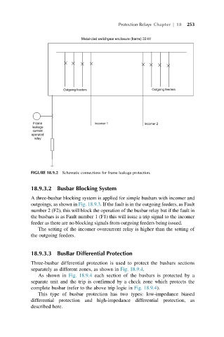
FIGURE 18.9.2 Schematic connections for frame leakage protection.
18.9.3.2 Busbar Blocking System
A three-busbar blocking system is applied for simple busbars with incomer and
outgoings, as shown in Fig. 18.9.3. If the fault is in the outgoing feeders, as Fault
number 2 (F2), this will block the operation of the busbar relay but if the fault in
the busbars is as Fault number 1 (F1) this will issue a trip signal to the incomer
feeder as there are no blocking signals from outgoing feeders being issued.
The setting of the incomer overcurrent relay is higher than the setting of
the outgoing feeders.
18.9.3.3 BusBar Differential Protection
Three-busbar differential protection is used to protect the busbars sections
separately as different zones, as shown in Fig. 18.9.4.
As shown in Fig. 18.9.4 each section of the busbars is protected by a
separate unit and the trip is confirmed by a check zone which protects the
complete busbar (refer to the above trip logic in Fig. 18.9.4).
This type of busbar protection has two types: low-impedance biased
differential protection and high-impedance differential protection, as
described here.