
Page 259 - Practical Power System and Protective Relays Commissioning
P. 259
256 Practical Power System and Protective Relays Commissioning
FIGURE 18.9.6 Simple high-impedance circulating current scheme with two current
transformers.
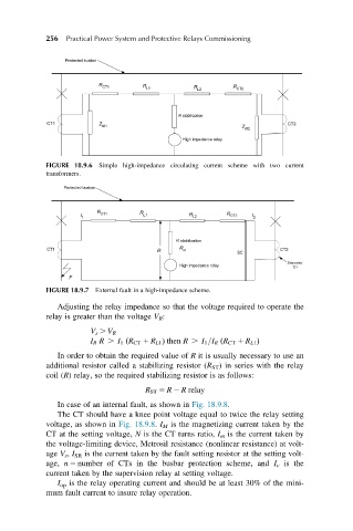
FIGURE 18.9.7 External fault in a high-impedance scheme.
Adjusting the relay impedance so that the voltage required to operate the
relay is greater than the voltage V R :
V s . V R
I R R . I 1 R CT 1 R L1 Þ then R . I 1 =I R R CT 1 R L1 Þ
ð
ð
In order to obtain the required value of R it is usually necessary to use an
additional resistor called a stabilizing resistor (R ST ) in series with the relay
coil (R) relay, so the required stabilizing resistor is as follows:
R ST 5 R 2 R relay
In case of an internal fault, as shown in Fig. 18.9.8.
The CT should have a knee point voltage equal to twice the relay setting
voltage, as shown in Fig. 18.9.8. I M is the magnetizing current taken by the
CT at the setting voltage, N is the CT turns ratio, I m is the current taken by
the voltage-limiting device, Metrosil resistance (nonlinear resistance) at volt-
age V s , I SR is the current taken by the fault setting resistor at the setting volt-
age, n 5 number of CTs in the busbar protection scheme, and I v is the
current taken by the supervision relay at setting voltage.
I op is the relay operating current and should be at least 30% of the mini-
mum fault current to insure relay operation.