
Page 76 - Practical Power System and Protective Relays Commissioning
P. 76
Transmission Lines Theory Testing and Commissioning Chapter | 6 73
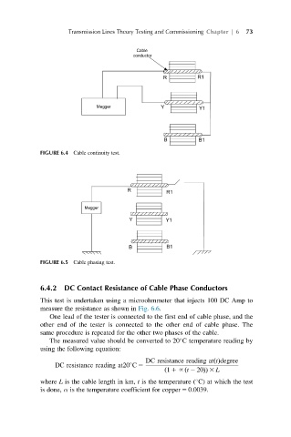
FIGURE 6.4 Cable continuity test.
FIGURE 6.5 Cable phasing test.
6.4.2 DC Contact Resistance of Cable Phase Conductors
This test is undertaken using a microohmmeter that injects 100 DC Amp to
measure the resistance as shown in Fig. 6.6.
One lead of the tester is connected to the first end of cable phase, and the
other end of the tester is connected to the other end of cable phase. The
same procedure is repeated for the other two phases of the cable.
The measured value should be converted to 20 C temperature reading by
using the following equation:
DC resistance reading at tðÞdegree
DC resistance reading at20 C 5
ð 1 1~ t 2 20ÞÞ 3 L
ð
where L is the cable length in km, t is the temperature ( C) at which the test
is done, α is the temperature coefficient for copper 5 0.0039.