
Page 234 - Practical Ship Design
P. 234
196 Chapter 7
For the model range of 1.5 x lo6 < R, < 2 x 1 O7
C, = [0.93 + 0.1377(10g R, - 6.3)2 - 0.06334(10g R, - 6.3)4]
x (O.O75/(log R, - 2)2 (7.13)
For the ship range of 10’ < R, < 4 x 1 O9
C, = [1.032 + O.O2816(10g R, - 8) - O.O06273(10g R, -8)2]
x (O.O75/(log R, - 2)2 (7.14)
The last factor in each of these equations is of course the ITTC’57 formula whilst
the first is a suitable modifier.
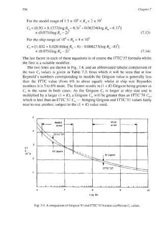
The two lines are shown in Fig. 7.4, and an abbreviated tabular comparison of
the two C, values is given in Table 7.3, from which it will be seen that at low
Reynold’s numbers corresponding to models the Grigson value is generally less
than the ITTC value (from 6% to about equal), whilst at ship size Reynolds
numbers it is 5 to 6% more. The former results in (1 + K) Grigson being greater as
C, is the same in both cases. As the Grigson C, is larger at ship size and is
multiplied by a larger (1 + K), a Grigson C,, will be greater than an ITTC’78 C,,,
which is less than an ITTC’57 C,, - bringing Grigson and ITTC’57 values fairly
near to one another, subject to the (1 + K) value used.
5
4
3
Cf
X
10-3
2
1
6 7 8 9 10
Log Rn
Fig. 7.4. A comparison of Grigson’93 and ITTC’57 friction coefficient C, values.