
Page 354 - Practical Well Planning and Drilling Manual
P. 354
Section 3 revised 11/00/bc 1/17/01 12:00 PM Page 330
[ ] Practical Wellsite Operations
3.1.8
During testing, compare readings on the various pressure gauges to
ensure that they are all working and reading the same. Sensators need
to be kept pumped up, and it is a good policy to have them knocked
off and to, at some point, check them before the stack test.
If the water in the stack cannot be incorporated into the mud sys-
tem (due to density or OBM in use, for example), the water can be
dumped as it returns when pipe is run in the hole. See Table 3-2 and
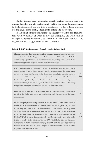
Figure 3-3 for a suggested BOP test procedure.
5
Table 3-2 BOP Test Procedure—Typical 13 / 8 in Surface Stack
Check accumulator fluid pressure, manifold pressure, regulated pressure, and reser-
voir level. Switch off the charge pumps. Drain the stack and fill with water. Pull the
wear bushing. Operate the BOPs from the accumulator, noting times to close BOPs
and resulting pressure drops on accumulator manifold gauge.
Run a cup-type tester on open pipe or HWDP to no deeper than the third joint of
casing. A stand of HWDP below the CTT may be needed to enter the casing. Open
the previous casing annulus side outlet. Check that the drillpipe can take the force 1a
exerted on the CTT at casing test pressure. Check that the stack is full. Close annu- Ann
lar, flush through the kill, and choke lines with water. Pressure test casing spool
outer valves through the kill line against outer choke manifold valves to the casing
test pressure when plug was bumped. Check side outlets for leaks.
Close the casing spool inner valves, open the outer valves. Bleed off after the test
period at the choke manifold, open annular, and pull the CTT. Close the previ- 1b
ous annulus.
Set the test plug in the casing spool on a test sub and drillpipe with a stand of
HWDP below. The test sub should be made up on the test plug hand tight only (if
the test plug is not solid, torque up a closed kelly cock underneath). Make up a side
outlet sub on the top of the drillpipe with the stab in kelly cock then the kelly made
up on top. Make up chiksans from the cement manifold to the side outlet. Lift the 2a
kill line NRV off its seat and remove the kill line. Open the casing spool side outlet TPR
in case of a leak past the test plug. Test the TPR, stab in kelly cock, kill line outer
manual, and choke line manual by pumping down DP with the stand pipe manifold
bleed off or kill valve open. (If there are spare kill and choke outlets below BPR, test
in parallel with the main outlets.)
330