Page 356 - Practical Well Planning and Drilling Manual
P. 356

Section 3 revised 11/00/bc  1/17/01  12:00 PM  Page 332


                      [     ]   Practical Wellsite Operations
                       3.1.8


                         Record the results on the blowout preventer test form.

                         The remote panels may be function tested as follows: switch off the recharge pumps,
                         close the valves from the accumulator bottles. Depressure the manifold with the
                         bleed valve and leave open until finished. Operate each function on the remote
                         panel and check whether the four-way valve moves correctly. When finished, line up
                         all four-way valves correctly, open up bottles, and switch on recharge pumps. This
                         method is fast since it prevents actual operation of the BOP units and preserves
                         accumulator pressure.


                         Check the active tank volumes against the driller’s gauges indicated volumes. Test
                         inside BOP with test sub while RIH.


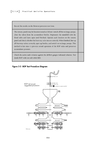
                       Figure 3-3  BOP Test Procedure Diagram

                                                            3b

                                                      3a  Upper Kelly Cock


                                                      2c  Lower Kelly Cock
                                  BOP test as per     2a  Stab In Kelly Cock
                                  suggested procedure
                                                             Connection to cement manifold
                                                                1a1b


                                                             Double ram unit with 13 5/8"
                                                             flanged connections
                                                                      2a2b2c
                                                                      4
                                     Kill Line  N R V             HCR  Choke Line
                                     4      2c  2a  2b         2a  2c   4

                                                             Single ram unit with 13 5/8"  3a3b
                                                             flange connections
                                           N R V                  HCR
                                             2c  2a  2b         2a  2c
                                   S Devereux   1a  1b          1b  1a


                                                     332
   351   352   353   354   355   356   357   358   359   360   361