
Page 255 - Pressure Vessel Design Manual
P. 255
Special Designs 233
= y3@ $ = 0.0443( 4.5 ) (g) = 32th = 32(0.75) = 24in. < 48in.
1
t" 27.3 x lo6 0.753
Ap = tbl = 0.75(24) = 18in2
= 0.092in. < 0.375in. bh3 1(43)
1 --=- = 5.33 in4.
- 12 12
Balance OK by inspection
0 Assume a layout where the maximum stiffener spacing
is 48. I=I,+-+L
A,Apy2
Apt:
12 A, +A,
1 b4 1
= 5.33 + 0.633 + 18.46 = 24.42 in.4
c -- ASY +fb
P-~,+~p 2
- 4(2.375) 0.75 =
--
+ - 0.807in.
22 2
c, = (h + tb) - c,
= 4 + 0.75 - 0.807 = 3.943
Check deflections:
k=t Item 235.2 1.04 1.49
s
Pn
b"
1
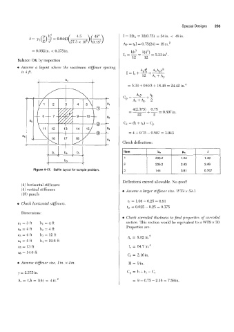
Figure 4-17. Baffle layout for sample problem. 2 235.2 2.43 3.49
0.767
144
3
3.81
Deflections exceed allowable. No good!
(4) horizontal stiffeners
(4) vertical stiffeners 0 Assume a larger stiffener size: WT9 x 59.3.
(18) panels
tf = 1.06 - 0.25 = 0.81
0 Check horizontal stifenem.
tw = 0.625 - 0.25 = 0.375
Dimensions:
Check corroded thickness to find properties of corrohd
al=3ft bl=4ft section. This section would be equivalent to a WT9 x 30.
a2 = 4 ft bz = 4 ft Properties are:
a,? = 4 ft b3 = 12 ft
A, = 8.82 in.'
= 4 ft b* = 19.6 ft
as = 13 ft I, = 64.7 in.4
% = 14.8 ft
C, = 2.16in.
e Assume stiflener size, 1 in. x 4 in. H = gin.
y = 2.375 in. C, = h + tl, - C,
A, = t,h = l(4) = 4in.' = 9 + 0.75 - 2.16 = 7.59in.