Page 256 - Pressure Vessel Design Manual
P. 256

234    Pressure Vessel Design Manual

                                                         Table 4-10
                              Summary of  Results for Stress and Deflection in Composite Stiffeners for Sample Problem


                     I         I         I          I         I         I          I         I         I


                     tb                                         e  Check thermal expansion of bafle.
             y=c --
                  p   2
                                                                       0.85PRr, - 0.85(250) 120.938
               = 7.215in.                                         Ai =         -                = 0.00054 in.
                                                                          tE      1.75(27.3 x lo6)
                                                                  A2 = R,a  AT = 120.938(7.124 x 10⁻⁶)430  = 0.370in.
                                                                  A3 = 0.5h AT = 0.5(240)(7.124 x 1OP6)430 = 0.367in.
               = 64.7 + 0.844 + 308.14 = 373.7in.4                A4 = A1 + A2 - A3
                                                                     = 0.00054 + 0.370 - 0.367 = 0.0035 < 0.06 in.
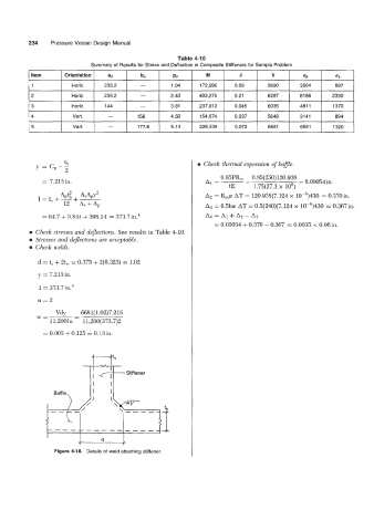
          e  Check stresses and dejections. See results in Table 4-10.
            Stresses and deflections are acceptable.
            Check welds.

             d = t, + 2tw = 0.375 + 2(0.323) = 1.02

             y = 7.215 in.
             I = 37~7in.~

             n=2
                   v+    = 6681( 1.02)7.215
             W=
                 11,200In   11,200(373.7)2
               = 0.005 + 0.125 = 0.13in.


                &                        Stiffener
                              I4 I
                                    I
                                    I
                  Baffle
                                    L
                YEP1
                   --_
                            -_-----__

                                       attaching
                        4-18.
                             Details
                                    weld
                                  of
                                              stiffener.
                  Figure
   251   252   253   254   255   256   257   258   259   260   261