
Page 250 - Pressure Vessel Design Manual
P. 250
228 Pressure Vessel Design Manual
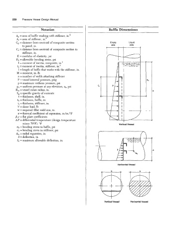
Notation Baffle Dimensions
Ap = area of baffle working with stiffener, ina2
A, = area of stiffener, in.2
C, = distance from centroid of composite section
to panel, in.
C, = distance from centroid of composite section to
stiffener, in.
E = modulus of elasticity, psi
Fb = allowable bending stress, psi
I = moment of inertia, composite, in?
I, = moment of inertia, stiffener, in.4
1 =length of baffle that works with the stiffener, in.
M =moment, in.-lb
n =number of welds attaching stiffener
P =vessel internal pressure, psig
p = maximum uniform pressure, psi
p, = uniform pressure at any elevation, a,, psi
R, =vessel mean radius, in.
S, = specific gravity of contents
t =thickness, shelI, in.
tb =thickness, baMe, in.
t, =thickness, stiffener, in.
V = shear load, Ib
w = required fillet weld size, in.
a = thermal coefficient of expansion, in./in.PF
p, y = flat plate coefficients
AT = differential temperature (design temperature
minus 70°F), OF Vertical Vessel
ab =bending stress in baffle, psi
a, =bending stress in stiffener, psi
An = radial expansion, in.
6 =deflection, in.
6, = maximum allowable deflection, in.
a
Horizontal Vessel
Vertical Vessel Horizontal Vessel