
Page 245 - Pressure Vessel Design Manual
P. 245
Special Designs 223
/I = location of maximum torsional moment from M, =vertical bending moment between posts due to
column, degrees force Q, in.-lb
I,,I, =moment of inertia, in.' M,, =overturning moment of vessel at base of ring
r =torsional shear stress, psi beam, in.-lb
B, =bearing pressure, psi Mp =horizontal bending moment at posts due to force
J =polar moment of inertia, in.4 F, in.-lb
M =bending moment in base plate due to bearing M, =vertical bending moment at posts due to force Q,
pressure, in.-lb in.-lb
MD = horizontal bending moment between posts due to MT =torsional moment at distance B from post, in.-lb
force F, in.-lb
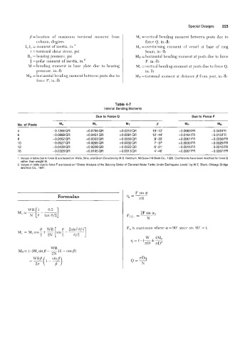
Table 4-7
Internal Bending Moments
Due to Force Q Due to Force F
No. of Posts M* Mc MT P MP MB
4 -0.1366 QR t0.0705 QR +0.0212QR 1 9"-12' +0.0683 FR -0.049 FR
6 -0.0889QR +OD451 QR +0.0091 QR 1 2"-44' +0.0164 FR -0.013 FR
8 -0.0662 QR +0.0333QR +0.0050QR 9"-33 +0.0061 FR -0.0058 FR
10 -0.0527 QR +0.0265 QR +0.0032 QR 7" -37' f0.0030 FR -0.0029 FR
12 -0.0438 QR f0.0228QR +0.0022 QR 6'-21' f0.0016 FR -0.0016 FR
16 -0.0328 QR +0.0165QR +0.0013QR 4-46' +0.0007 FR -0.0007 FR
1. Values in table due to force Q are based on Walls, Bins, and Grain Elevators by M.S. Ketchum, McGraw-Hill Book Co., 1929. Coefficients have been modified for force Q
rather than weight W.
2. Values in table due to force F are based on "Stress Analysis of the Balcony Girder of Elevated Water Tanks Under Earthquake Loads" by W.E. Black; Chicago Bridge
and Iron Co., 1941.
F sin 4
Formulas 9t =7
0.5 ]
- WR [1
M -- 2F sin a,,
N 8 tan 8/2 F1,z ... =
N
0 WR [ 0 2sin20/4 F,, is maximum where a = 90" since sin 90" = 1.
M, = M,cos-+- sin-- 1
2 2N 2 012
WR
MT= (-)M,sin B - -(1 - cos B)
2N
\YRB( l-- si;">
+-
2Tr