
Page 246 - Pressure Vessel Design Manual
P. 246
224 Pressure Vessel Design Manual
Load Diagrams
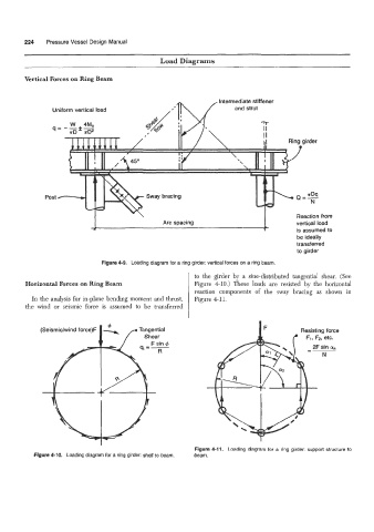
Vertical Forces on Ring Beam
Intermediate stiffener
Uniform vertical load
Reaction from
vertical load
is assumed to
be ideally
transferred
to girder
Figure 4-9. Loading diagram for a ring girder: vertical forces on a ring beam.
to the girder by a sine-distributed tangential shear. (See
Horizontal Forces on Ring Beam Figure 4-10.) These loads are resisted by the horizontal
reaction components of the sway bracing as shown in
In the analysis for in-plane bending moment and thrust, Figure 4-11.
the wind or seismic force is assumed to be transferred
(Seismic/wind forc
Figure 4-11. Loading diagram for a ring girder: support structure to
Figure 4-10. Loading diagram for a ring girder: shell to beam. beam.