Page 248 - Pressure Vessel Design Manual
P. 248

226    Pressure Vessel Design Manual


                                                                              L


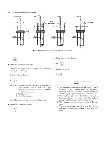
                                       Figure 4-14.  Dimensions and loadings for various ring girders.


                                                               e  Moment for semi$xed  span.

                                                                      B,L~
                                                                 M=-
            Additional  bending in base plate,                         10
            Additional bending  occurs in base plate  due to localized   e Bending stress, fb.
            bearing of post on ring.
                                                                      6M
            Bearing pressure,  B,,  psi                          fb =-
                                                                      t2


                                                                                     Notes
            where  A  =  assumed  contact  area,  area  of  cap  plate  or                    ~
                      cross-sectional  area  of  post.  See  Figure   1. The shell of a column-supported tank, vessel, or bin is
                      4-14.  Assume  reaction  is  evenly  distributed   considered  to  be  a  “circular  girder”  or  “ring beam”
                      over the contact  area.                        uniformly loaded over its periphery and supported by
                   l = Cantilever, in.                               columns equally spaced on the ring circumference.
                   L = Semifued span, in.                         2. The ring beam  (girder) is subjected to compression,
                                                                     bending, and torsion due to the weight of the tank and
            Note: Maximum bending is at center of base plate.        contents and horizontal wind or seismic force.
                                                                  3. The  maximum  bending  moment  occurs  at  the  sup-
          e  Moment for cantilever portion.                          ports.
                                                                   4. The  torsional  moment  MT will be  0 at the  supports
                 BPI2                                                and  maximum at angular  distance fl away from sup-
            M=-                                                      ports.
                  2
   243   244   245   246   247   248   249   250   251   252   253