
Page 244 - Pressure Vessel Design Manual
P. 244
222 Pressure Vessel Design Manual
PROCEDURE 4-5
DESIGN OF RING GIRDERS [8-121
The circular girder supports the weight of the tank, vessel,
or bin; its contents; and any installed plant equipment. The
ring beam will take the load from the vessel uniformly dis-
tributed over its full circumference, and in turn will be sup-
ported on a structural steel framework in at least four places.
The shell of a column-supported tank, vessel, or bin can
be considered as a ring beam whether or not there is a
special built-up beam structure for that purpose.
Horizontal seismic force is transferred from the shell or
short support skirt to the ring beam by tangential shear. The
girder performs the function of transmitting the horizontal
shear from the tank shell to the rods and posts of the sup-
porting structure.
The girder is analyzed as a closed horizontal ring acted
upon by the horizontal shear stresses in the tank shell and by
the horizontal components of the stresses in the rods and
posts in the top panel of the supporting steel framework.
Maximum girder stresses generally occur when the direc-
tion of the earthquake force is parallel to a diameter passing
through a pair of opposite posts.
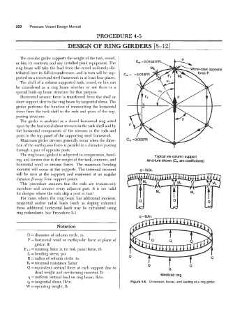
The ring beam (girder) is subjected to compression, bend- Typical six-column support
ing, and torsion due to the weight of the tank, contents, and structure shown (C, are coefficients)
horizontal wind or seismic forces. The maximum bending
moment will occur at the supports. The torsional moment q - Iblin.
will be zero at the supports and maximum at an angular
distance away from support points.
This procedure assumes that the rods are tension-only
members and connect every adjacent post. It is not valid
for designs where the rods skip a post or two!
For cases where the ring beam has additional moment,
tangential and/or radial loads (such as sloping columns)
these additional horizontal loads may be calculated using
ring redundants. See Procedure 5-1.
~
Notation
D = diameter of column circle, in.
F =horizontal wind or earthquake force at plane of
girder, lb
Fl,z = resisting force in tie rod, panel force, lb
fb =bending stress, psi
R = radius of column circle, in.
R, =torsional resistance factor I
Q = equivalent vertical force at each support due to Q Q
dead weight and overturning moment, Ib
q = uniform vertical load on ring beam, lbhn. Idealized ring
qt =tangential shear, lb/in. Figure 4-8. Dimension, forces, and loading at a ring girder.
W = operating weight, Ib