
Page 69 - Pressure Vessel Design Manual
P. 69
52 Pressure Vessel Design Manual
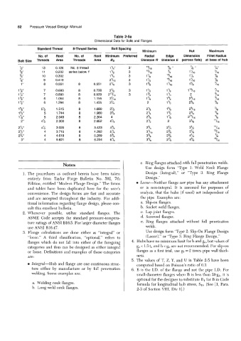
Table 2-5a
Dimensional Data for Bolts and Flanges
Standard Thread 8-Thread Series Bolt Spacing
Minimum Nut Maximum
No. of Root No. of Root Minimum Preferred Radial Edge Dimension Fillet Radius
Bolt Size Threads Area Threads Area Bs Distance R Distance E (across flats) at base of hub
13 0.126 No. 8 thread 3‘ 13 11 6
11 0.202 series below 1’ 3 15 11 6
10 0.302 3 1 lI8
9 0.41 9 3 I ’I4
8 0.551 8 0.551 3 I 3i8
7 0.693 8 0.728 3 1 112 1 13i16 ’4 6
7 0.890 8 0.929 3 1 ’14 2
6 1.054 8 1.155 1 ’18
6 1.294 8 1.405 2
5% 1.515 8 1.680 2118
5 1.744 8 1.980 2 ’i4
5 2.049 8 2.304 23i8
4% 2.300 8 2.652 2112
4% 3.020 8 3.423 23/4
4 3.715 8 4.292 3‘116
4 4.61 8 8 5.259 3318
4 5.621 8 6.234 3”18
Notes c. Ring flanges attached with full penetration welds.
Use design form “Type 1: Weld Neck Flange
1. The procedures as outlined herein have been taken Design (Integral),” or “Type 3: Ring Flange
entirely from Taylor Forge Bulletin No. 502, 7th Design.”
Edition, entitled “Modern Flange Design.” The forms Loose-Neither flange nor pipe has any attachment
and tables have been duplicated here for the user’s or is non-integral. It is assumed for purposes of
convenience. The design forms are fast and accurate analysis, that the hubs (if used) act independent of
and are accepted throughout the industry. For addi- the pipe. Examples are:
tional information regarding flange design, please con- a. Slip-on flanges.
sult this excellent bulletin. b. Socket weld flanges.
2. Whenever possible, utilize standard flanges. The c. Lap joint flanges.
ASME Code accepts the standard pressure-tempera- d. Screwed flanges.
ture ratings of ANSI B16.5. For larger diameter flanges e. Ring flanges attached without full penetration
use ANSI B16.47. welds.
3. Flange calculations are done either as “integral” or Use design form “Type 2: Slip-On Flange Design
“loose.” A third classification, “optional,” refers to (Loose),” or “Type 3: Ring Flange Design.”
flanges which do not fall into either of the foregoing 4. Hubs have no minimum limit for h and go, but values of
categories and thus can be designed as either integral g, < 1.5 t, and h < g, are not recommended. For slip-on
or loose. Definitions and examples of these categories flanges as a first trial, use gl = 2 times pipe wall thick-
are: ness.
5. The values of T, Z, Y, and U in Table 2-5 have been
Integral-Hub and flange are one continuous struc- computed based on Poisson’s ratio of 0.3.
ture either by manufacture or by full penetration 6. B is the I.D. of the flange and not the pipe I.D. For
welding. Some examples are: smalldameter flanges when B is less than 20gl, it is
optional for the designer to substitute B1 for B in Code
a. Welding neck flanges. formula for longitudinal hub stress, SH. (See [I, Para.
b. Long weld neck flanges. 2-3 of Section VIII, Div 11.)