
Page 70 - Pressure Vessel Design Manual
P. 70
General Design 53
7. In general, bolts should always be used in multiples of the bolt spacing becomes more critical. The spacing
4. For large-diameter flanges, use many smaller bolts factor can be less than required for circular flanges
on a tight bolt circle to reduce the flange thickness. since the metal available in the corners tends to
Larger bolts require a large bolt circle, which greatly spread the bolt load and even out the moment.
increases flange thickness. 10. Design flanges to withstand both pressure and external
8. If the bolt holes are slotted to allow for swing-away loads, use “equivalent” pressure P, as follows:
bolting, substitute the diameter of the circle tangent
16M
to the inner edges of the slots for dimension A and P --+-+P 4F
follow the appropriate design procedures. e- nG3 nG2
9. Square and oval flanges with circular bores should be
treated as “inscribed” circular flanges. Use a bolt circle where M =bending moment, in.-lb
passing through the center of the outermost bolt holes. F = radial load. Ib
The same applies for noncircular openings; however,
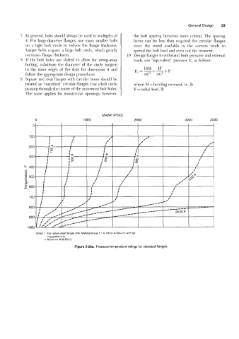
MAWP (PSIG)
0 1000 2000 3000 3500
Notes: 1. For carbon steel flanges only. Material Group 1.1 A-105 or A-350-LF2 with flat
ring gasket only.
2. Based on ANSI 816.5.
Figure 2-20a. Pressure-temperature ratings for standard flanges.