
Page 75 - Pressure Vessel Design Manual
P. 75
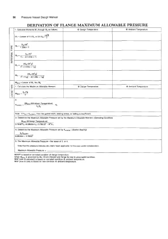
56    Pressure Vessel Design Manual

                    DERIVATION OF FLANGE MAXIMUM ALLOWABLE PRESSURE

           1. Calculate Moments M,  through M5 as follows:   I   @  Design Temperature   I   @  Ambient Temperature

           MI = (Lesser of 1.5 Sf,  or 2.5 Sfa)  &I: B
                                 f
                                ~
                Sf,hBt2
           M2  =-
               I .33te + 1
                  SfohBt2
           M3 =
               YA  - Z(1.33te + 1)

                 2StoABt2g:
           Mq =
               f?+(l.33te  + 1)g:


           MMAX = Lesser of  MI  thru M5
           1. Calculate the Maximum Allowable Moment   @  Design Temperature             @  Ambient Temperature


                                             I                                  I
           2.
                  ~MMAX( @Ambient Temperature)
           &(MAX)  =                  - Ab
                          hGSa
           Note : If Am2>Am(MA~), then the gasket width, seating stress, or bolting is insufficient.
           3. Determine the Maximum Allowable Pressure set by the Maximum Allowable Moment: (Operating Condition)
                M~m(@Design Temperature)
           0.785B2hD+6.28bGmh~+0.785(G2 - B')h,
           4.  Determine the Maximum Allowable Pressure set by Am(~~x): (Gasket Seating)
               SbAm(MAX)
           6.28bGm + 0.785G2

           5. The Maximum Allowable Pressure = the lesser of 3. or 4.
             Note that this pressure includes any static head applicable for the case under consideration.
             Maximum Allowable  Pressure =
           MAWP is based on corroded condition at design temperature.
           When MMAX is governed by Mz: Check integral type flange for new & uncorroded condition.
           MAP (cold & corroded) is based on corroded condition @  ambient temperature.
           MAP (new & cold) is based on new condition @ ambient temperature.