
Page 76 - Pressure Vessel Design Manual
P. 76
General Design 57
PROCEDURE 2-8
DESIGN OF SPHER CALLY DISHED COVERS
Design pressure. P AllomM str#rw
Design temperature Flange Bolting
flange material Design temp., !& Design temp., S,
Boltina material Amb. temD.. St, I Amb. temD.. S. I
2 GASKET AND FACING DETAILS
Gasket I Facing
R TABLES 2-3 AND 24 LOAD AND BOLT CAWLATIONS
HI, - wB2P/4 hD = 0.qC - B) MD = Hoh~
HG = HP he O.xc - G) MG = HG~G
HT = H - HD hT - 0.5(hD + hG) Mi = HThT
Hr = Hdtsn 81 hr M, 9 Hrhr
8 Calculation
B
b1 = arc sin - Mo = MD + MG + MT~M,
Note: Mr is ( + ) if C of head is below the center
2L + t of gravity; ( - ) if above.
Ho - W I hG IM. = WhG
7 FLANQE AND HEAD THICKNESS CALCULATION
Head Thickmu Required
Diameter of
where M = M, bolts
or ML, whichever
is greater
HTI HG
A
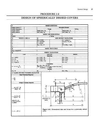
Figure 2-21. Dimensional data and forces for a spherically dished
T=F+- cover.