
Page 78 - Pressure Vessel Design Manual
P. 78
General Design 59
PROCEDURE 2-10
BOLT TORQUE REQUIRED FOR SEALING FLANGES [ 10-131
PT =test pressure, psi
Notation F = restoring force of gasket (decreasing compression
force) from initial bolting strain, lb
Ah = cross-sectional area of bolts, Fho = initial tightening force, Ib
A, = actual joint-contact area of gasket, in.2 & = effective length of bolt, mid nut to mid nut, in.
b = effective gasket seating width, in. W = total tightening force, lb
d = root diameter of threads, in. W,1= H + H, = required bolt load, operating, lb
d,, =pitch diameter of threads, in. W,z = required bolt load, gasket seating, lb
G = diameter at location of gasket load reaction, in. y = gasket unit seating load, psi
M = external bending moment, in.-lb H =total hydrostatic end force, lb
m = gasket factor HP = total joint-contact surface compression load, lb
N =gasket width, in. T =initial tightening torque required, ft-lb
n = number of bolts t, =thickness of gasket, in.
El, = modulus of elasticity of bolting material at tempera- t, =thickness of nut, in.
ture, psi K =total friction factor between bolthut and nut/ flange
E, = modulus of elasticity of gasket material at tempera- face
ture, psi w =width of ring joint gasket, in.
P = internal pressure, psi
P, = equivalent pressure including external loads, psi Note: See Procedure 2-7 for values of G, N, m, b, and y.
P, = radial load, lb
YAPL
W e- I
1L x$$
Tongue and groove
k4.J Raised face
Ring joint
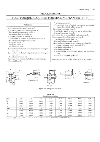
Figure 2-23. Flange and joint details.
Size %, in. '/8 in. 1 in. 1% in. 1% in. 1% in. 1% in. 1% in.
d 0.6273 0.7387 0.8466 0.9716 1.0966 1.2216 1.3466 1.4716
dm 0.6850 0.8028 0.9188 1.0438 1.1688 1.2938 1.4188 1.5438
t" 0.7344 0.8594 0.9844 1.1094 1.2188 1.3438 1.4688 1.5938
Size 1% in. 1% in. 2 in. 2% in. 2% in. 2% in. 3 in. 3Y4 in.
d 1.5966 1.7216 1.8466 2.0966 2.3466 2.5966 2.8466 3.0966
dm 1.6688 1.7938 1.9188 2.1688 2.4188 2.6688 2.9188 3.1688
t" 1.71 88 1.8438 1.9688 2.2031 2.4531 2.7031 2.9531 3.1875
~~~