
Page 83 - Pressure Vessel Design Manual
P. 83
64 Pressure Vessel Design Manual
1 < (1.1 -?)a Case 4 (Figure 2-29)
or
I 1
for length 2 6 and taper is 4:l minimum.
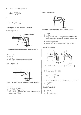
Figure 2-29. Case 4: Screwed flat head [l , Section UG-34(c)].
Case 2 (Figure 2-27)
1. C=0.3
2. r 2 3th
3. Design threads with 4:l safety factor against failure by
shear, tension, or compression due to hydrostatic end
force.
4. Seal welding optional.
5. Threads must be as strong as standard pipe threads.
Case 5 (Figure 2-30)
Figure 2-27. Case 2: Forged head [l , Section UG-34(b-1)].
1. C=0.17
2. tf 1 2t,
3. r 2 3tf
4. For forged circular or noncircular heads.
Case 3 (Figure 2-28)
Figure 2-30. Case 5: Lap welded head [l , Section UG-34(c)].
1. Circular heads: C = 0.13 if
e > (1.1 -?)A
fh
2. Noncircular heads and circular heads regardless of
Figure 2-28. Case 3: Integrally forged head [l , Figure 6-34 (b-2)]. e : c = 0.2.
3. r 13th
Case 6 (Figure 2-31)
1. C = 0.33 m but > 0.2
2. r 2 0.375in. if t, 5 1.5in. 1. C=0.13
3. r 3 0.25ts if t, is greater than Sin. but need not be 2. d 5 24in.
greater than 0.75in. 3. 0.05 < tlJd < 0.25