
Page 87 - Pressure Vessel Design Manual
P. 87
68 Pressure Vessel Design Manual
PROCEDURE 2-12
~~
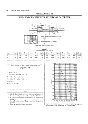
REINFORCEMENT FOR STUDDING OUTLETS
Figure 2-40. Typical studding outlet.
Table 2-9
Tapped Hole Area Loss, S, in.'*
ds % in. % in. '/8 in. lin. 1% in. 12, in. 1% in. 1% in. 1% in. 1% in. 1% in. 2in. 2% in.
X 1.11 1.33 1.55 1.77 2.00 2.44 2.66 2.88 3.10 3.32 3.56
S 1.28 1.84 2.50 3.28 4.15 5.12 6.20 7.38 8.66 10.05 11.55
1 00
Calculation of Area of Reinforcement
(Figure 2-40) 0 95
0 90
A = (dt,F) + S
L = Greater of d or R, + t, + t 0 85
A1 = 2(L - R, - t,)(t - t,)
0 80
A2 = 2(tp - h - tr)(t, - tm) LL
L
A3 = 2(ht,) 5075
-
AT=AI+AZ+AB 2
0 70
0 65
Notes
0 60
1. Check plane which is nearest the longitudinal axis of
the vessel and passes through a pair of studded holes. 0 55
2. Sb=allowable stress of stud material at design tem-
perature. 050 1
Sf, = allowable stress of flange material at design tem- 0" 10" 20" 30" 40" 50" 60" 70" 80" 90"
perature. Anqla of plane with Longitudinal Axis
3. A2 as computed ignores raised face. Figure 2-41. Chart for determining the value of F. (Reprinted by permis-
sion from ASME Code, Section VIII, Div. 1, Figure UG-37.)