
Page 84 - Pressure Vessel Design Manual
P. 84
General Design 65
r
fh
Bevel optional
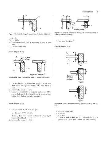
Figure 2-33. Case 8: Welded flat heads (Full penetration welds re-
Figure 2-31. Case 6: Integrally forged head [l, Section UG-34(d)]. quired) [l , Section UG-34(g)].
4. 4, L ts
5. r 2 0.25t1,
6. Head integral with shell by upsetting, forging, or spin- 3. See Note 3 in Case 7
ning.
7. Circular heads only. Case 9 (Figure 2-34)
Case 7 (Figure 2-32)
-1 Type 1
Projection optional '
Backing
Figure 2-32. Case 7: Welded flat heads [l , Section UG-34(e)(f)]. strip may
be used
1. Circular heads: C = 0.33 m but 2 0.2. If m < 1, then
shell cannot be tapered within 2& from inside of
head.
2. Noncircular heads: C = 0.33
3. Liquid penetrant (L.P.) or magnetic particle test (M.T.)
end of shell and O.D. of head if t, or th is greater than
1/2 in. thick (before and after welding).
Case 8 (Figure 2-33) Figure 2-34. Case 9: Welded flat heads [l , Section UG-34(h), UW-13.2
(f)(g)l.
1. Circular heads: C = 0.33 m but 20.2.
1. Circular heads only.
tl,
t, > 2t, and > 1.25tS but I 2. C=O.33
If in < 1, then shell cannot be tapered within 2& 3. t, 2 1.25tr
from inside of head. 4. L.P./M.T. end of shell and O.D. of head if t, or th is
2. Noncircular heads: C = 0.33 greater than 1/2 in. thick (before and after welding).