
Page 79 - Pressure Vessel Design Manual
P. 79
60 Pressure Vessel Design Manual
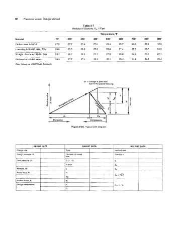
Table 2-7
Modulus of Elasticity, Eb, 1 O6 psi
Temperature, 'F
Material 70" 200" 300" 400" 500" 600" 700" 800" 900"
Carbon steel A-307-B 27.9 27.7 27.4 27.0 26.4 25.7 24.8 23.4 18.5
Low alloy A-1 93-87, B16, B7M 29.9 29.5 29.0 28.6 28.0 27.4 26.6 25.7 24.5
Straight chrome A-193-B6, B6X 29.2 28.7 28.3 27.7 27.0 26.0 24.8 23.1 22.1
Stainless A-1 93-88 series 28.3 27.7 27.1 26.6 26.1 25.4 24.8 24.1 23.4
Note: Values per ASME Code, Section II.
1 AF = change in joint load
due to the gasket relaxing
m
--
AL -,
Elongation - Compression
*-
Figure 2-24. Typical joint diagram.
DESIGN DATA GASKET DATA BOLTING DATA
Flange size I TY Pe Nominal size
Design pressure, P Diameter of raised Quantity n
face
~
O.D., 1.D. d
N or w I d,
Moment, M I
Radial load, Pr I
~
Friction factor, K
Design temperature