Page 77 - Pressure Vessel Design Manual
P. 77

58    Pressure Vessel Design Manual


                                                  PROCEDURE 2-9
                     DESIGN OF BLIND FLANGES WITH OPENINGS [ 1, 41


            I1                                        DESIGN CONDITIONS
             Designpressure, P   I           1                         Allowable slr6cMI.
             Desian temoerature   I                        flange            I             Bolting
            I  mama material   I             IDesian temn.. stn   I          IDesian temo., sh   I
             Boning material                 IAtm. temp., sl.   I            IAtm. temp., S.   I


             3        TABLES 2-3 AND 24       4                   LOAD AND BOLT CALCULATIONS
              N                               WM  = bffiy                     A,,,  = greater of
              b                               Hp I 2bdmP                     ' WdS. or Wmd%
             G (see below)                    H = G2rP14                      Ab
             Y                                Wmi  = Hp + H                   W   O.!5(Am  + &)Sa
              m                                                               hG  = 0.qC - G)


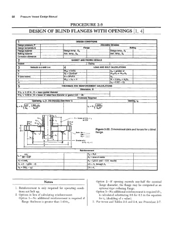
                                                                    Figure 2-22. Dimensional data and forces for a blind
                                                      Bolts: NO.-  __   flange.
                                                     -   ma.--
                                                         R-  -
                                                      Greater of d
                                                          orA.+I,,+t


                                                         Reinforcement
                  PR,                                         A3 = 2tnh
             L=- SE - 0.6P                                    A4  = area of welds
              4 P0.W                                          & = L(0.D. pad - O.D. node)
              A1  =(t-tO)(h-d)                                EA = A,  through A5
              Az  = 2h(t, - m)                                EA >Ar


                                Notes                               Option  2-If   opening  exceeds  one-half  the  nominal
                                                                      flange dameter, the flange may be computed  as an
            1. Reinforcement  is  only  required  for  operating  condi-   optional-type  reducing flange.
              tions not bolt up.                                    Option &No  additional reinforcement is required if to
            2.  Options in lieu of calculating reinforcement:         is calculated substituting 0.6 for 0.3 in the equation
              Option  1-No   additional  reinforcement  is  required  if   for to (doubling of c value).
                flange thickness is greater than  1.414 to.      3.  For terms and Tables 2-3 and 2-4. see Procedure 2-7.
   72   73   74   75   76   77   78   79   80   81   82