
Page 81 - Pressure Vessel Design Manual
P. 81
62 Pressure Vessel Design Manual
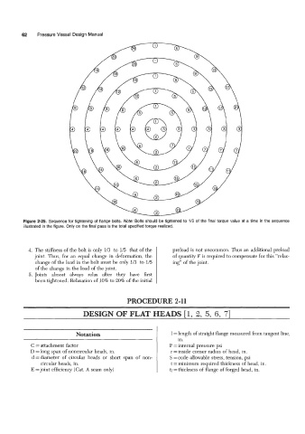
Figure 2-25. Sequence for tightening of flange bolts. Note: Bolts should be tightened to 1/3 of the final torque value at a time in the sequence
illustrated in the figure. Only on the final pass is the total specified torque realized.
4. The stiffness of the bolt is only 1/3 to 1/5 that of the preload is not uncommon. Thus an additional preload
joint. Thus, for an equal change in deformation, the of quantity F is required to compensate for this “relax-
change of the load in the bolt must be only 1/3 to 1/5 ing” of the joint.
of the change in the load of the joint.
5. Joints almost always relax after they have first
been tightened. Relaxation of 10% to 20% of the initial
PROCEDURE 2-11
DESIGN OF FLAT HEADS 11, 2. 5. 6. 71
Notation 1 =length of straight flange measured from tangent line,
in.
~
C = attachment factor P = internal pressure psi
D = long span of noncircular heads, in. r =inside comer radius of head, in.
d=diameter of circular heads or short span of non- S =code allowable stress, tension, psi
circular heads, in. t = minimum required thickness of head, in.
E =joint efficiency (Cat. A seam only) tf= thickness of flange of forged head, in.