Page 85 - Pressure Vessel Design Manual
P. 85

66    Pressure Vessel Design Manual

            5. Type 1: al+az>2t,
                     0.5a2  c al < 2a2                                                        Retaining
              Type 2: a > 2t,                                                                    ring
              Type 3: a+b>2t,                                                                  fh
                     b = 0 is permissible


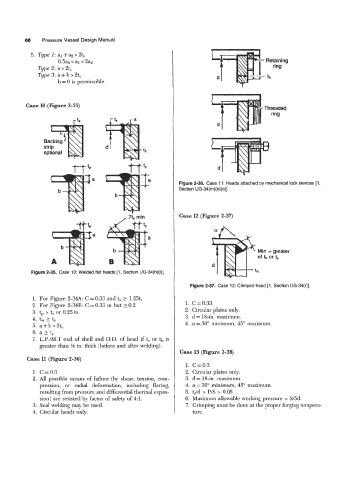
          Case 10 (Figure 2-35)                                                               Threaded
                                                                                                ring


                Backing                                                    L
                strip
                optional

                                                                             d


                                                                Figure 2-36.  Case 11: Heads attached by mechanical lock devices [l,
                                                                Section UG-34(m)(n)(o)].


                                                                Case 12 (Figure 2-37)


                                  a

                                                                                            Min = greater
                                                                                            of  th or 1,
                                                                           d @th
            Figure 2-35.  Case 10: Welded flat heads [l, Section UG-34(h)(i)].

                                                                    Figure 2-37.  Case 12: Crimped head [l, Section UG-34(r)].

             1.  For Figure 2-34A  C = 0.33 and t, 2 1.25tr
            2. For Figure 2-34B: C = 0.33 m but 2 0.2             1. C=0.33
            3. tp > t, or 0.25in.                                 2. Circular plates only.
            4.  tw 2 ts                                           3.  d= &in.  maximum.
            5.  a-tb>2tS                                          4.  a = 30" minimum, 45" maximum.
            6.  a 2 t,
             7.  L.P./M.T  end of  shell and O.D. of  head  if t,  or th is
               greater than M in. thick (before and after welding).
                                                                Case 13 (Figure 2-38)
           Case 11  (Figure 2-36)
                                                                  1. C=0.3
             1. C=0.3                                             2.  Circular plates only.
             2.  All  possible  means  of failure  (by shear, tension,  com-   3. d = 18-in. maximum.
               pression,  or  radial  deformation,  including  flaring,   4.  01  = 30" minimum, 45" maximum.
               resulting from pressure and differential thermal expan-   5.  t,/d  > P/S  > 0.05
               sion) are resisted by factor of safety of 4:l.     6.  Maximum allowable working pressure  e S/5d.
             3.  Sed welding may be used.                         7.  Crimping must be done at the proper forging tempera-
             4. Circular heads only.                                 ture.
   80   81   82   83   84   85   86   87   88   89   90