
Page 88 - Pressure Vessel Design Manual
P. 88
General Design 69
PROCEDURE 2-13
DESIGN OF INTERNAL SUPPORT BEDS 18, 91
Notation
Hold down or
A = cross-sectional area of bolt, in. 2 balls
AT = total area supported by beam, In'
I3 =ratio of actual force to allowable force per inch of
weld
1) =width of bearing bar, grating, in.
d = depth of bearing bar, grating, in.
D =vessel inside diameter, ft
E = modulus of elasticity, in.
F =total load of bed, lb Ring
FI, = allowable bending stress, psi
F, = minimum specified yield strength, psi Beam seat
wf =fillet weld size, in.
h =height of beam seat or length of clip, in.
I = moment of inertia, in. 4 P
K = distance from bottom of beam to top of fillet of web,
in. [Y]
= length of beam, width of ring, or unsupported width
of grating, ft or in.
M =bending moment, in.4
N = minimum bearing length, in. 1
n = number of bolts
P = concentrated load, lb
AP = differential pressure between top and bottom of bed,
(-1 up, (+I down, psi
p =uniform load, psf
R =end reactions, lb
R, = root area of bolts, in. 2
S = allowable shear stress in bolts or fillet welds, psi
t =thickness of clip, gusset, or ring, in.
w = uniform load, lb/ft
Z = section modulus, in. 3 Some applicatmns
F, = equivalent concentrated load, lb in this area
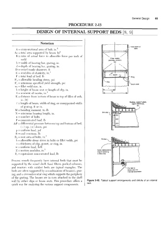
Process vessels frequently have internal beds that must be
supported by the vessel shell. Sand filters, packed columns,
and reactors with catalyst beds are typical examples. The
beds are often supported by a combination of beam(s), grat- lhermal expansion
ing, and a circumferential ring which supports the periphery
of the grating. The beams are in turn attached to the shell
wall by either clips or beam seats. This procedure offers a Figure 2-42. Typical support arrangements and details of an internal
quick way for analyzing the various support components. bed.