
Page 92 - Pressure Vessel Design Manual
P. 92
General Design 73
Ring (Figure 2-47) Case 1: single beam-l=0.5D
Case 2: two beams-l= 0.333D
b =width of bearing bar (corroded), in,
d =depth of bearing bar (corroded), in.
12M
Zreqd = ~
Ft,
Proposed bearing bar size:
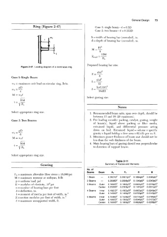
Figure 2-47. Loading diagram of a continuous ring.
nbd2
Z=-
Case 1: Single Beam 6
I=- nbd3
wg = maximum unit load on circular ring, lb/in. 12
PD
w? -- 6= 5~C(12l)~
4 384EI
M = w3.e
Select grating size.
t=/- 6M
Fh
Notes
Select appropria--. ring size. 1. Recommended beam ratio, span over depth, should be
between 15 and 18 (20 maximum).
Case 2: Two Beams 2. For loading consider packing, catalyst, grating, weight
of beam(s), liquid above packing or filter media,
entrained liquid, and differential pressure acting
down on bed. Entrained liquid =volume x specific
gravity x liquid holdup x free area x 62.4 lb per cu ft.
3. Minimum gusset thickness of beam seat should not be
less than the web thickness of the beam.
4. Main bearing bars of grating should run perpendicular
to direction of support beams.
Select appropriate ring size.
Table 2-1 1
~
Grating Summary of Forces and Moments
No. of
Beams Beam AT FT R M
F1, = maximum allowable fiber stress = 18,000 psi
M = maximum moment at midspan, ft-lb 1 Beam - 0.39270' 0.3927pD2 0.1864pd 0.0565pD3
p = uniform load, psf 2 Beams - 0.2698D2 0.2698pD2 0.1 349pD2 0.0343pD3
E = mocMus of elasticity, lo6 psi 3 Beams Outer 0.1 850D' 0.1850pD' 0.0925pD2 0.0219~0~
n =number of bearing bars per foot Center 0.2333D2 0.2333pD2 0.1 167pD' 0.031 lpD3
6 =deflection, in. 4 Beams Inner 0.19250' 0.1925pD' 0.0963pD' 0.0240pD3
I = moment of inertia per foot of width, in.4 Outer 0.1 405D' 0.1 405pD2 0.0703pD' 0.0143pD3
Z = section modulus per foot of width, in.3 5 Beams Inner 0.1548D' 0.1548pD' 0.0774pD' 0.0185pD3
C =maximum unsupported width, ft. Outer 0.1092D' 0.1 092pD' 0.0546pD2 0.0107pD3
Center 0.1655D2 0.1655pD' 0.0828pD' 0.0208pD3