
Page 91 - Pressure Vessel Design Manual
P. 91
72 Pressure Vessel Design Manual
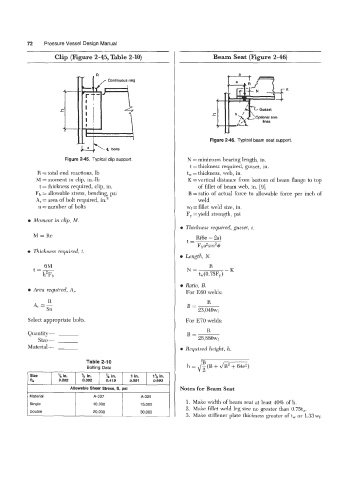
Clip (Figure 2-45, Table 2-10) Beam Seat (Figure 2-46)
I c hr I Gusset 1 K
! ;-
L
/
Optional trim
* Figure 2-46. Typical beam seat support.
-
lines
bolts
Figure 2-45. Typical clip support. N = minimum bearing length, in.
t =thickness required, gusset, in.
R =total end reactions, lb t, = thickness, web, in.
M =moment in clip, in.-lb K =vertical &stance from bottom of beam flange to top
t =thickness required, clip, in. of fillet of beam web, in. [9]
Fb = allowable stress, bending, psi B =ratio of actual force to allowable force per inch of
A, = area of bolt required, in.' weld
n = number of bolts wf= fillet weld size, in.
F, =yield strength, psi
0 Moment in clip, M.
e Thickness required, gusset, t.
M = Re R(6e - 2a)
t=
Fba2sin2#
e Thickness required, t.
e Length, N.
6M R
t=- N= -K
h2Fb tW(0.75F,)
e Ratio, B.
0 Area required, A, For E60 welds:
R
A, = g B= R
23,040wf
Select appropriate bolts. For E70 welds:
Quantity - B= R
Size - 26,880wf
Material - rn Required height, h.
Size 78 in. % in. in. 1 in. 1% in.
R. 0.202 0.302 0.41 9 0.551 0.693
I Allowable Shear Stress, S, psi I Notes €or Beam Seat
I Material I A-307 1 ~ A-3r 1
1. Make width of beam seat at least 40% of h.
Single 10,000 15,000
2. Make fillet weld leg size no greater than 0.75tW.
Double 20,000 30,000
3. Make stiffener plate thickness greater oft, or 1.33wf.