
Page 95 - Pressure Vessel Design Manual
P. 95
76 Pressure Vessel Design Manual
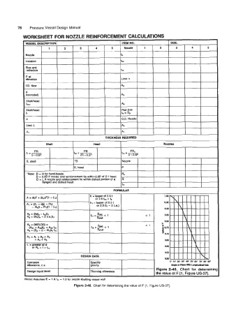
WORKSHEET FOR NOZZLE REINFORCEMENT CALCULATIONS
IhpkotP*nemthla@udwAxis
Figure 248. Chart for determinin!
Design liquid level Thinning allowance
the value of F [l , Figure UG-371.
Notes: Assumes E = 1 8 f,, = 1 .O for noule abutting vessel wall
Figure 2-48. Chart for determining the value of F [l, Figure UG-371.