
Page 99 - Pressure Vessel Design Manual
P. 99
80 Pressure Vessel Design Manual
Notes 3. The method employed in this procedure is to disregard
the shell attached to the outside diameter of the flat
1. This procedure is only applicable for integrally at- head and then analyze the flat head with a central
tached flat heads with centrally located openings opening.
which exceed one-half the head diameter. For appli- 4. This procedure is based on appendix 14 of ASME
cable configurations see sketches in ASME Code, Section VIII, Division 1.
Figures UG-34(a), (b-I), (b-2), (d), or (g).
2. For details where inside corner of shell-head juncture
is machined to a radius: gl = go and f = 1.
PROCEDURE 2-16
FIND OR REVISE THE CENTER OF GRAVITY OF A VESSEL
Notation
C = distance to center of gravity, ft or in.
D’ =revised distance to C.G., ft or in.
, L5 / d,=distance from original C.G. to weights to add or
, L4 / remove, (+) or (-) as shown, ft or in.
L3 Ln =distance from REF line to C.G. of a component
J weight, ft or in.
, L2/ W,=weight of vessel component, contents or at-
(-)dl
&l+ +d2 b tachments, Ib
Y
~
+ W’ =new overall weight, lb W + or - Cw,,
W =overall weight, Ib,
W,
w w, = revised unit weights, lb (+) to add weight
z
-I (-) to remove weight
LL
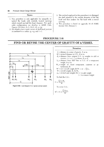
w 77 7 7 7 7 To find the C.G.:
U
w1 w2 w3 w4 w5 w6
, C t
4
To revise C.G.: