
Page 101 - Pressure Vessel Design Manual
P. 101
82 Pressure Vessel Design Manual
Formulas Step 3: Determine if any components must be impact tested
in their proposed material grade and thickness. This would
establish the MDMT.
Step 4: Establish the overall MDMT as the highest value of
MDMT for each of the component parts.
Notes
= t, - C.a.
Tz = (1 - R)100 1. For flat heads, tubesheets, and blind flanges, the thick-
MDMT = TI - Tz ness used for each of the respective thickness’ is that
thickness divided by 4.
2. For comer, fillet, or lap-welded joints, the thickness
Procedure used shall be the thinner of the two parts being joined.
3. For butt joints, the thickness used shall be the thickest
Step 1: Determine the lowest anticipated temperature to joint.
which the vessel will be subjected. 4. For any Code construction, if the vessel is stress re-
Step 2: Compare the lowest combined pressure-temperature lieved and that stress relieving was not a Code re-
case with the MDMT for each component. quirement, the MDMT for that vessel may be
reduced by 30” without impact testing.
Table 2-12 31’ 7
Determination of MDMT (Example)
SDT S.
Part ksi t” tc ksi Ti
- - -
Shell SA-51 6-70 B 17.5 16.6 1 .oo 0.869 0.823 0.875 13.97
Head(1) SA-51 6-70 B 17.5 16.6 0.857 0.653 0.620 0.732 14.89 21.8
10” Noz(2) SA-53-B B 12.8 12.2 0.51 9 0.174 0.166 0.394 5.26 -5.18
10” 300# Flg. (4) SA-1 05 B 17.5 16.6 0.519 0.128 0.121 0.394 5.26 -5.18
30” Blind (5) SA-266-2 B 17.5 16.6 6.06 1.48 5.94 - 51” 105” -54”
30” Body Flg. SA-266-2 B 17.5 16.6 4 Same as Shell .I +11
Wear PL SA-51 6-70 B 17.5 16.6
Bolting SA-1 93-87 - - -
Notes:
1. The governing thickness for heads is based on that portion of the head which is NPS 10 SCH Bo PIPE (t 0.5ws)
in tension. For a 2:l S.E. head this is the crown position where R = 0.90. (SA.53, OR%. WELDED)
2. Includes pipe 12%% under tolerance.
3. Thickness exclusive of C.a.
4. Thickness at the hub (weld attachment) governs.
5. The governing thickness of flat heads and blind flanges is 1/4 of actual thick-
ness.
6. Since the tension stress in the wear plate is less than the tension stress in the
shell, the MDMT for the shell will govern.
1’ MK SADDLE BAND
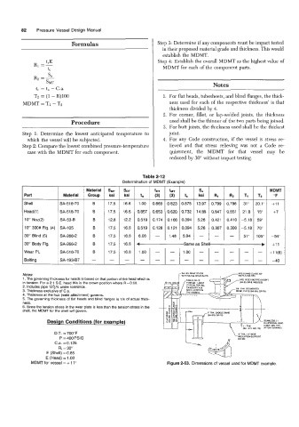
Design Conditions (for example) ELLIPSOIDAL HEAD
(0 857~ MIN. THK.
D.T. = 700°F
P = 400 PSlG
C.a. =0.125
Ri = 30”
E (Shell) = 0.85
E (Head) = 1 .OO
MDMT for vessel = + 110 Figure 2-53. Dimensions of vessel used for MDMT example.