
Page 106 - Pressure Vessel Design Manual
P. 106
General Design 87
One can imagine a thin-walled cylinder loaded axially to Stiffening Rings
the maximum extent possible. An inward circumferential
load does not add any force longitudinally to the cylinder; Stiffening rings, either internal or external, should be
however, it increases the risk of buckling. spaced at between 1 and 4 diameters. For vessels with stif-
fening rings, the length of the cylinder is determined by the
Safety Factor distance between the stiffening rings. This presupposes that
the stiffening rings are of adequate size and stiffness to resist
The allowable buckling stress is the “critical buckling the forces imposed on them. The design of the stiffening
stress” multiplied by some factor of safety. The safety rings is not a part of this procedure.
factor for buckling ranges from 1.5:l to 3:l. In addition,
certain upper boundaries are specified, such as one-half
the yield strength.
ALLOWABLE BUCKLING STRESS IN CYLINDRICAL SHELLS 114-201
Data
A = metal cross-sectional area, in. 2
B =ASME Code allowable stress, psi
C =end connection coefficient, use 1.0 for simply sup-
ported and 2.0 for cantilevered
C, = max allowable slenderness ration per AWWA D-100
D, = OD of cylinder, in.
E = modulus of elasticity, psi
e =tolerance for peaking, in.
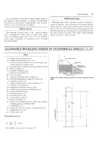
FS = factor of safety Slenderness ratio, Ur
Fy = minimum specified yield strength, psi Figure 2-57. Graph showing comparison of column types with critical
Fb = allowable longitudinal compressive stress, psi
I = moment in inertia, in. 4
L, =length at which critical stress is achieved, in.
1 =tolerance for banding, in.
M = longitudinal bending moment, in.-lb
P, = critical external pressure buckling load, psi
P,, = critical buckling load, Ib
Pi =internal pressure, psi
P, = external pressure, psi
R, =vessel outside radms, in.
r = radius of gyration, in.
T, = factor for transition between elastic and inelastic
buckling point per AWWA D-100 A
t =wall thickness, in.
W =weight of vessel above plane of consideration, lb
a, =longitudinal stress, psi
a,., = critical stress, psi
Allowable Stress, Fb -x-
7-
For ASME Code vessels, Fb = Factor “B”