
Page 108 - Pressure Vessel Design Manual
P. 108
General Design 89
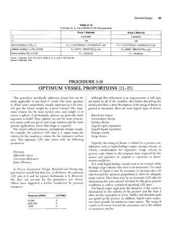
Table 2-15
Formulas for Fb from AWWA D-100 Requirements
Group 1 Materials Group 2 Materials
Tc 0.0031088 0.0035372
CC 138 126
Elastic buckling 0 e t/R, e T, Fb= 17.5(lO5)(VR,)[(I +50,000(t/R0)*]=psi Fb= 17.5(lO5)(VRO)[1 +50,000(L'R,)2] =psi
Inelastic buckling T, c VR, e 0.01 25 Fb = [5775 + 738(103)(VRo)] = psi Fb = [6925 + 886(103)(t/R,)] =psi
Plastic buckling t/Ro> 0.0125 Fb = 15,000 psi Fb = 18,000 psi
Group 1 materials: A131 Gr A & B; A283 Gr B. C, and D; A573 Gr 58.
Group 2 materials: A36.
PROCEDURE 2-19
OPTIMUM VESSEL PROPORTIONS 121-251
This procedure specifically addresses drums but can be Although this refinement is an improvement, it still does
made applicable to any land of vessel. The basic question not factor in all of the variables. But before describing the
is: What vessel proportions, usually expressed as UD ratio, actual procedure, a brief description of the sizing of drums in
will give the lowest weight for a given volume? The maxi- general is warranted. Here are some typical types of drums:
mum volume for the least surface area, and weight, is of
course a sphere. Unfortunately, spheres are generally more Knock-out drums.
expensive to build. Thus, spheres are not the most econom- Accumulator drums.
ical option until you get to very large volumes and for some Suction drums.
process applications where that shape is required. Liquid-vapor separators.
For vessels without pressure, atmospheric storage vessels, Liquid-liquid separators.
for example, the optimum LJD ratio is 1, again using the Storage vessels.
criteria for the maximum volume for the minimum surface Surge drums.
area. This optimum LJD ratio vanes with the following
parameters: Typically the sizing of drums is related to a process con-
sideration such as liquid holdup (surge), storage volume, or
velocity considerations for separation. Surge volume in
Pressure. process units relates to the response time required for the
Allowable stress. alarms and operators to respond to upstream or down-
Corrosion allowance. stream conditions.
Joint efficiency.
For small liquid holdup, vessels tend to be vertical, while
for large surge volumes they tend to be horizontal. For small
In Process Equipment Design, Brownell and Young sug- volumes of liquid it may be necessary to increase the L/D
gest that for vessels less than 2 in. in thickness, the optimum ratio beyond the optimum proportions to allow for adequate
LJD ratio is 6 and for greater thicknesses is 8. However, surge control. Thus there may be an economic UD ratio for
this does not account for the parameters just shown. determining the least amount of metal for the given process
Others have suggested a further breakdown by pressure
categories: conditions as well as a practical operating UD ratio.
For liquid-vapor separators the diameter of the vessel is
determined by the velocity of the product and the time it
Pressure (PSIG) LID Ratio takes for the separation to occur. Baffles and demister pads
can speed up the process. In addition, liquid-vapor separa-
0-250 3 tors must provide for minimum vapor spaces. The sizing of
250-500 4
>500 5 vessels is of course beyond this discussion and is the subject
of numerous articles.