Page 97 - Pressure Vessel Design Manual
P. 97

78    Pressure Vessel Design Manual

                                                  PROCEDURE 2-15

                       DESIGN OF LARGE OPENINGS IN FLAT HEADS 111


                                                                                            i
                                                                            htegraC                     A
                                                                             nozzle  1
                              Notation                                     opening with     €
                                                                                   &  opening Loose- with-
              P =internal pressure, psi
            Mo =bending  moment in head, in.-lb                                                   out nozzle
            Mh = moment acting on end of hub or shell at juncture,
                 in.-lb
            MD =component  of moment M,  due to HD, in.-lb
            MT =component  of moment  M,  due to HT, in.-lb
             H =hydrostatic  end force, lb
            HD =hydrostatic  end force on area of central opening, lb
             HT=H-HD,  lb
             SH =longitudinal  hub stress, psi
             SR =radial  stress in head, psi
             ST =tangential  stress in head, psi                                                         B
            SHS =longitudinal  hub stress, shell, psi                             Ho
            SRS =radial  stress, head, at O.D., psi
            STS =tangential  stress, head, at O.D., psi
            SHO = longitudinal hub stress at central opening, psi
            SRO = radial stress, head, at central opening, psi
            STO =tangential  stress, head, at central opening, psi
           Z, Z1, Y, T, U, F, V,  f, e, d, L, XI, and 8 are all factors.
                                                                                                            H
                          Factor Formulas
            1. Calculate geometry factors:

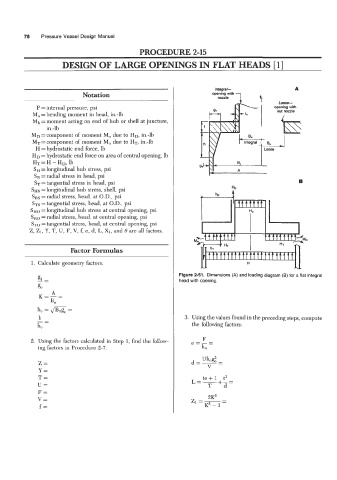
                                                               Figure 2-51.  Dimensions (A) and loading diagram (B) for a flat integral
                                                               head with opening.


                                                                 3. Using the values found in the preceding steps, compute
                                                                    the following factors:


            2.  Using the factors calculated in Step 1, find the follow-
              ing factors in Procedure  2-7.

              Z=
              Y=
              T=                                                        te + 1  t3
              U=                                                    L=-   T  f-=
                                                                               d
              F=
              V=                                                    z1=-   2K2   -
                                                                               -
               f=                                                       K2 - 1
   92   93   94   95   96   97   98   99   100   101   102