
Page 179 - Pressure Swing Adsorption
P. 179
ii
154 PRESSURE SWING ADSORPTION EQUILIBRIUM THEORY 155
Thus, to find the ultimate axial position of the shock front at any pressure ,.o
requ1res a sequence of steps: the mitial conditions give a; then the cornoosi-
0.9
tion ahead the shock .front can be found from
0.8
(4.74) C 0.7
.£ V
0
0.6
(which is e.ssentially the same as Eqs. 4.32 and 4.50); next the cornoos1tion ..!!
behind the shock can be determmed from Eq. 4.73; and finally the axial 0 • 0.5 b
oosition can be computed from ::,;
0.4
C
• a
0,
~ 0.3
( 4.75) 0 X
0.2
O.i
(which 1s essentially the same as Ea. 4.33) usmg the comoosition shift at the
trailing edge of the shock front. 0.0
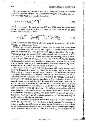
To illustrate the o6int, it is approoriate to cornoare such results with those 0.0 0.2 0.4 0.6 0.8 1.0
obtamed by fimte difference techniques. Figure 4.23 shows predictions of the
previous equations -and those presented by Rousar and Diti 31 for oxygen Ax101 Distance From Inlet: z/L
enrichment. It can be seen that the enctpomts coincide, as does much of all Figure 4.23 Composition profiles durmg pressunzat1on of a bed of zeoiite 5A, to
three profiles. The ormcioal distinction ts due to rounding, which is inher- which vanous mixtures of oxygen and nitrogen are admitted. P = 6 atm. Initial
ently due to dispersion being included in the numerically derived results. conditions: (a) Yo.,= 0.1, (b) y 02 = 0,21, (c) }'o, = 0.60. f3 =·0.517. Numei-ical results
from Rousar and Ditl. 31
All the results shown for the equilibrium theory were obtained with a calcul-
ator in several mmutes time. Similar results have been obtained by Flores i
Fernandez and Kenney, 25 and are shown in Figure 3.2.
If we turn our attention now to blowdown, and still restnct conditions to j imtial composit1on and position of a particular characteristic. For a given set
Jocai equilibrium; it is ciear that blowdown 1s simpler than pressunzation. of mitial conditions, 1t 1s easiest to choose a final composition y, then to
That is because there 1s no interaction between the initiai and boundary ! determine the necessary pressure ratio P, and finally the ultimate axial
conditions. Furthennore, m previous sect10ns of this chapter, the mit1a1 i position z. Otherwise (i.e., given the pressure ratio), a root-finding procedure
condition _prior to blowctown was usually taken to be uniform, which led to 1s needed to determme the final comoos1t1on.· When the mit1al comoosition
relativeiy ·simple material balance calcuiations. Some subtleties anse for the orofile is uniform, Ea. 4.75 mdicates that there will be no axrnl composition
case of pressurizatioil with feed (cf. Section 4.4.2), when dead volume at the gradient as the pressure falls. Regardless, Eas. 4.18 and 4.19 can be used
product end was considered (cf. Section 4.4.6), and when the heat effects with the compos1tion-oosition-oressure mformation to determine the aver-
ac~ompanymg blowdown were found to be deletenous (cf. Section 4.8). The age composition and quantity of the effluent ctunng, blowctown. To relate
most imp<?rtant feature of blowdown ts the effluent comoosition, which m these to flow rates, It would be necessary to select a depressunzation rate:
most mstances con,tinuou;;Iy changes as pressure falls, except when a nnse s1mplisl!cally dP /dt = constant, or somewhat more realist1cally, d In P /dt =
steJ? prece9es blow~own, yielding the pure heavy component throughout constant, alt~ough any operatmg policy can be accommodated.
blQwdown. Aµother topic of pr,actical mterest 1s the ultimate composition In the models Presented earlier m this chapter, the pressure gradient
profile m .the bed followmg blowdown. through the column 1s assumed to be negligible. In that s1tuat1on the basic
If the milial composition profile 1s known, applying the local equilibrium equations governing pressurization and blowdown steps are not much more
mc:1ctel for systems with linear lSOtherms 1s f~irly simple. For example, in complicated than those for steps at constant pressure. Negiedmg pressure
order to predict the ~ffluent composition during blowdown or the residual drop is reasonable for most convent1onai PSA units, but 1t 1s clearly mappro-
interstitial. gas composition following blowdown, one need only apply charac- onate for single column, rapid pressure swing processes, which are discussed
,tenst1c eQuatmns such as Eqs. 4.74 and 4.75, where y and z represent the
0 0 m Section 7.3. The detailed modeling of pressunzat1on and blowdown steps,