
Page 149 - Principles and Applications of NanoMEMS Physics
P. 149
3. NANOMEMS PHYSICS: Quantum Wave Phenomena 137
2 Z 1
t
T = '
Z 2 . (187)
ε ε ε
The overall transmission coefficient for the 1 / 2 / 1 of Fig. 3-25(b) is given
by,
T Total = t Total 2 = T 2
2
+ 1 R −2 Rcos 2 k d . (188)
2
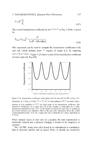
This expression can be used to compute the transmission coefficient of the
ε
unit cell, which includes finite 1 regions of length d /2, by replacing
1
kd → ( k d + kd )
2 1 1 2 2 . Figure 3-26 shows a plot of the transmission coefficient
of such a unit cell, Eq.(188).
1.
1.0 0
Transmission Coefficient Transmission Coefficient 0.
0.
0.8 8
0.6 6
0.4 4
0.
0.
0.2 2
0.0 0
0.
0 0 1 1 2 2 3 3 4 4 5 5 6 6 7 7 8 8
U n it C e ll P h a se S h ift (k d +k d )/(π /2
U n it C e ll P h a se S h ift (k d +k d )/(π /2 ) )
1 1
2 2
2 2
1 1
Figure 3-26. Transmission coefficient versus phase shift for unit cell for PBC in Fig. 3-25.
ε ε
Parameters: d =1.06in, d =0.42in, 1 =1, 2 =8.9. At odd multiples of π /2 one finds valleys,
1 2
whereas at even multiples of π / 2 one finds peaks of the transmission coefficient. The
destructive interference, of a single unit cell in this example, is responsible for a valley
transmission amplitude of only ~0.36. As the number of consecutive unit cells, N, making up
the crystal increases, the cumulative effect of the unit cell’s attenuation drives the overall
crystal attenuation from ~0.36, for a single unit cell, to arbitrarily low values, depending on
N. [161].
When multiple layers of unit cells are cascaded, the total transmission is
drastically reduced and a photonic bandgap is formed at the frequency in
question.
The 1-D PBC, being most often found in its embodiment as a multilayer
film in dielectric mirrors and in optical filters, is already an extensively