Page 326 - Principles of Applied Reservoir Simulation 2E
P. 326

Part  V: Technical  Supplements  31!


       Gas
                        I.JB
                a         g  g   Qok  +  ( so\Qak  +  ( SW\Q Wk     (30,3)
                                                   R
                                        R
                          0
                             ° > k
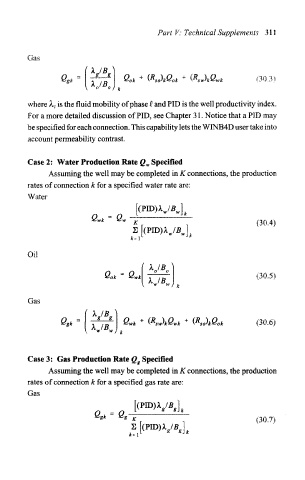
       where  is the  fluid mobility of phase  Q. and PID  is the well productivity index.
             A. c
       For a more detailed  discussion  of PID, see Chapter 31. Notice that a PID may
       be specified for each connection. This capability lets the WINB4D user take into
       account  permeability  contrast.


       Case 2:  Water Production  Rate Q w Specified
             Assuming the well may be completed in K connections,  the production
       rates of connection k for a specified water rate are:
       Water


                        Qwk  =  Qw
                                   K                                (30.4)
                                   S  /"DTT\\ 1  / D
                                       "LU i At
                                      (
                                              I Jo
                                   , _ . L   w  W J k
       Oil
                            e   =   w                               (30 5)
                             °*   ^ *  T^/if                           -

       Gas


                 •^^      ? ?  g P  ^-J  /T»  \  /-k  .  /•»>  \  /-V
                                  /  ,  +  (K  )L{S  ,  +  (R  ) k\s  .  /3Q  5)
                        MB.


       Case 3:  Gas Production Rate Q g  Specified
             Assuming the well may be completed  in K connections,  the production
       rates of connection  k for a specified gas rate are:
       Gas

                         Q    =  Q
                         *k    *
   321   322   323   324   325   326   327   328   329   330   331