
Page 297 - Process Equipment and Plant Design Principles and Practices by Subhabrata Ray Gargi Das
P. 297
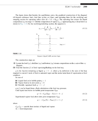
11.4 Fractionator   299


                  The figure shows that besides the equilibrium curve, the graphical construction of the diagonal
               (45 degrees reference line), feed line (q-line or f-line), and operating lines for the rectifying and
               stripping section for operating reflux ratio (R ¼ 1.5   R min ). The operating line relates the liquid
               composition (x n ) on stage ‘n’ with the composition of vapour (y nþ1 ) approaching tray n from below as
               shown in Fig. 11.9. For the rectifying/enriching section, the equation is

                                                     R          x D
                                                                                            (11.1)
                                                   R þ 1      R þ 1
                                            y nþ1 ¼      x n þ
                                         y
                                          n         x n–1
                                                                   Stage ‘n’


                                           y n+1       x
                                                        n
                                                                   Stage ‘n+1’

                                          y            x n+1
                                           n+2
               FIGURE 11.9
                                          VapoureLiquid traffic across trays.

                  The construction steps are
                (i) Locate the feed ðz F Þ, distillate ðx D Þ and bottom ðx B Þ stream compositions on the x-axis of the x-y
                   diagram.
               (ii) Find the fraction ðfÞ of feed vaporizing/flashing on the feed tray.
                  q is the fraction remaining as liquid: q ¼ 1   f, where q by definition is the ratio of the heat
               required to convert 1 mole of feed to saturated vapor and the molar latent heat of vaporisation at feed
               condition.
                  In case of
                  (a) Liquid feed at its bubble point q ¼ 1
                  (b) Vapour feed at its dew point q ¼ 0
                  (c) Partially vaporised feed: q ¼ 1   f
                  q or f can be found from a flash calculation at the feed tray pressure.
                  Cold liquid feed below its bubble point temperature T BPF
                                          q ¼ 1 þ C pL ðT BPF   T F Þ=l ¼ 1   f             (11.2)
                  Superheated vapour feed above dew point temperature T DPF
                                          q ¼  C pV ðT F   T DPF Þ=l ¼ 1   f                (11.3)
               where

                  C pL; C pV ¼ specific heat (molar) of liquid and vapour
                  T F ¼ feed temperature