
Page 332 - Process Equipment and Plant Design Principles and Practices by Subhabrata Ray Gargi Das
P. 332
334 Chapter 11 Distillation
(A) Cooling Cooling
water in water out
Condenser
EQUALISER line
to condenser
shell Reflex (B) Condenser
line
Cooling Water
3-way valve to
control reflux
Distillate
Tray
column
Distillate Vapour Packed
column
Steam
Condensate Reboiler
Change
still Liquid Bottoms
Steam
Bottoms
Condensate
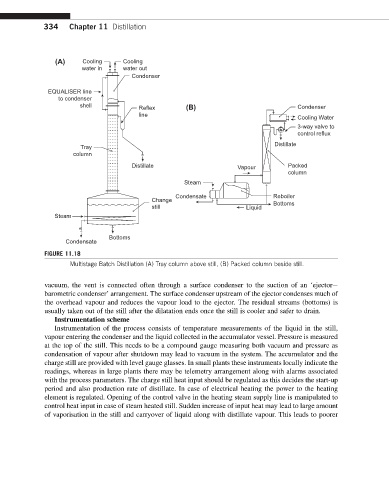
FIGURE 11.18
Multistage Batch Distillation (A) Tray column above still, (B) Packed column beside still.
vacuum, the vent is connected often through a surface condenser to the suction of an ‘ejectore
barometric condenser’ arrangement. The surface condenser upstream of the ejector condenses much of
the overhead vapour and reduces the vapour load to the ejector. The residual streams (bottoms) is
usually taken out of the still after the dilatation ends once the still is cooler and safer to drain.
Instrumentation scheme
Instrumentation of the process consists of temperature measurements of the liquid in the still,
vapour entering the condenser and the liquid collected in the accumulator vessel. Pressure is measured
at the top of the still. This needs to be a compound gauge measuring both vacuum and pressure as
condensation of vapour after shutdown may lead to vacuum in the system. The accumulator and the
charge still are provided with level gauge glasses. In small plants these instruments locally indicate the
readings, whereas in large plants there may be telemetry arrangement along with alarms associated
with the process parameters. The charge still heat input should be regulated as this decides the start-up
period and also production rate of distillate. In case of electrical heating the power to the heating
element is regulated. Opening of the control valve in the heating steam supply line is manipulated to
control heat input in case of steam heated still. Sudden increase of input heat may lead to large amount
of vaporisation in the still and carryover of liquid along with distillate vapour. This leads to poorer