
Page 327 - Process Equipment and Plant Design Principles and Practices by Subhabrata Ray Gargi Das
P. 327
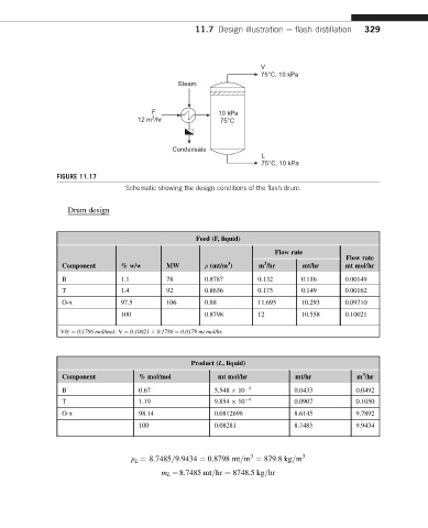
11.7 Design illustration e flash distillation  329


                                                                   V
                                                                   75°C, 10 kPa
                                              Steam


                                       F                10 kPa
                                       3
                                    12 m /hr             75°C


                                            Condensate
                                                                   L
                                                                   75°C, 10 kPa
               FIGURE 11.17
                                 Schematic showing the design conditions of the flash drum.


                  Drum design


                                                  Feed (F, liquid)
                                                                      Flow rate
                                                                                        Flow rate
                                                          3
                                                                    3
                 Component     % w/w       MW        r (mt/m )    m /hr      mt/hr      mt mol/hr
                 B             1.1         78        0.8787       0.132      0.116      0.00149
                 T             1.4         92        0.8636       0.173      0.149      0.00162
                 O-x           97.5        106       0.88         11.695     10.293     0.09710
                               100                   0.8798       12         10.558     0.10021

                V/F ¼ 0.1786 mol/mol; V ¼ 0.10021   0.1786 ¼ 0.0179 mt mol/hr.


                                                 Product (L, liquid)
                                                                                            3
                 Component          % mol/mol           mt mol/hr          mt/hr           m /hr
                 B                  0.67               5.548   10  4       0.0433          0.0492
                 T                  1.19               9.854   10  4       0.0907          0.1050
                 O-x                98.14              0.0812698           8.6145          9.7892
                                    100                0.08281             8.7485          9.9434


                                                                3
                                  r ¼ 8:7485=9:9434 ¼ 0:8798 mt=m ¼ 879:8kg=m 3
                                   L
                                          m L ¼ 8.7485 mt=hr ¼ 8748.5 kg=hr