
Page 326 - Process Equipment and Plant Design Principles and Practices by Subhabrata Ray Gargi Das
P. 326
328 Chapter 11 Distillation
stream yield. Therefore, the optimum P corresponding to a T is the one with 0.5% w/w benzene in the
liquid phase.
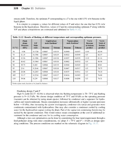
It is simpler to compute x i values for different values of P and select the one that has 0.5% w/w
benzene in the liquid phase. Therefore, values of T and its corresponding optimum P along with the
V/F and phase compositions are estimated and tabulated in Table 11.12.
Table 11.12 Results of flashing at different temperature and corresponding optimum pressure.
Flash Liquid-phase Vapour-phase %w/w %w/w
drum V/F mole fractions a mole fractions a Benzene Yield of
Pressure Mole in bottom bottom
o
T( C) (kPa) ratio Benzene Toluene Benzene Toluene product product
70 9.08 0.1728 0.0067 0.0119 0.0540 0.0357 0.49 82.94
75 11.14 0.1786 0.0067 0.0119 0.0522 0.0349 0.5 82.37
80 13.56 0.1906 0.0067 0.0118 0.0497 0.0339 0.49 81.16
85 16.42 0.1964 0.0067 0.0118 0.0482 0.0332 0.5 80.58
90 19.75 0.202 0.0068 0.0119 0.0468 0.0325 0.5 80.01
95 23.6 0.2146 0.0067 0.0118 0.0447 0.0317 0.5 78.75
100 28.06 0.2203 0.0068 0.0118 0.0435 0.0311 0.5 78.18
105 33.17 0.2334 0.0067 0.0117 0.0416 0.0303 0.5 76.88
110 39.04 0.239 0.0068 0.0117 0.0406 0.0298 0.5 76.31
a
Ortho-xylene mole fraction to be found by balance.
Finalising design T and P
High % yield (82.37e82.94) is observed when the flashing temperature is 70e75 C and flashing
pressure is 9e11.5 kPa. We choose design condition of 75 C and 10 kPa as the operating pressure
(vacuum) can be obtained by using steam ejector, followed by condenser and a separator for hydro-
carbon and water/condensate. Steam consumption increases substantially at higher vacuum (pressure
below w10 kPa), thus increasing the ejector size/capacity, condenser size (area) and generates more
condensate contaminated with hydrocarbon. One may also consider a condenser cooled by cooling
water for the hydrocarbon vapour exiting the drum. Part of the vapour not condensing therein may be
sucked by the ejector condenser. This would reduce steam consumption at the cost of additional in-
vestment for the condenser and cost for its cooling water consumption.
Although a true cost optimisation can be done by considering the heat input requirement through a
feed preheater along with other considerations, we adopt T ¼ 75 C and P ¼ 10 kPa as design oper-
ating conditions. The process conditions are marked on the schematic diagram in Fig. 11.17.