
Page 331 - Process Equipment and Plant Design Principles and Practices by Subhabrata Ray Gargi Das
P. 331
11.8 Batch distillation 333
liquid is collected in the accumulator vessel. Since the distillate gradually gets heavier, it can be
collected at different time intervals as batches of product with the desired composition. For example,
the equilibrium vapour composition corresponding to 50 mol % benzene in liquid (at w1 atm pres-
sure) is about 70 mol %. Therefore, batch distilling a feed mixture of 50:50 mol ratio benzene and
toluene can produce distillate batches with 60% benzene, 55% benzene, etc., collected at different time
intervals for appropriate durations. Different quality of distillates may be collected in different
accumulator vessels. The quality of the distillate is judged from the samples of distillate collected and
also from the temperature of the vapour entering the condenser. This is usually a simple system with a
heated still and a condenser operating around atmospheric pressure. Such a configuration produces
poor separation with either high or low concentrations of light component and involves fairly large
energy expenditure. The performance can be improved by operating the still at a lower pressure but an
2
operating pressure (P op ) lower than 0.1 kg/cm (abs) significantly increases the ejector steam con-
sumption for creating vacuum and the option becomes uneconomical. Redistillation of distillate in
subsequent batches can also be performed to obtain higher distillate purity.
On a different note, in small-scale batch distillation set ups with only the still and condenser,
equivalent number of vapoureliquid contacting stages is slightly more than one. This happens due to
the heat loss from the rising vapour through the equipment wall and its partial condensation providing
reflux that aids the separation. The ASTM D86
distillation test apparatus for light petroleum cuts
thus provides separation closely equivalent to 1.1
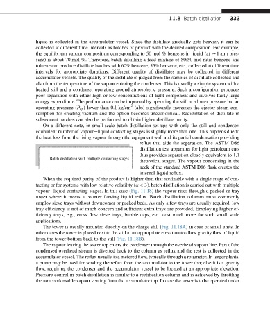
Batch distillation with multiple contacting stages
theoretical stages. The vapour condensing in the
neck of the standard ASTM D86 flask creates the
internal liquid reflux.
When the required purity of the product is higher than that attainable with a single stage of con-
tacting or for systems with low relative volatility ða < 3Þ, batch distillation is carried out with multiple
vapoureliquid contacting stages. In this case (Fig. 11.18) the vapour rises through a packed or tray
tower where it meets a counter flowing liquid reflux. Batch distillation columns most commonly
employ sieve trays without downcomer or packed beds. As only a few trays are usually required, low
tray efficiency is not of much concern and sufficient extra trays are provided. Employing higher ef-
ficiency trays, e.g., cross flow sieve trays, bubble caps, etc., cost much more for such small scale
applications.
The tower is usually mounted directly on the charge still (Fig. 11.18A) in case of small units. In
other cases the tower is placed next to the still at an appropriate elevation to allow gravity flow of liquid
from the tower bottom back to the still (Fig. 11.18B).
The vapour leaving the tower top enters the condenser through the overhead vapour line. Part of the
condensed overhead stream is diverted back to the column as reflux and the rest is collected in the
accumulator vessel. The reflux usually is a metered flow, typically through a rotameter. In larger plants,
a pump may be used for sending the reflux from the accumulator to the tower top; else it is a gravity
flow, requiring the condenser and the accumulator vessel to be located at an appropriate elevation.
Pressure control in batch distillation is similar to a rectification column and is achieved by throttling
the noncondensable vapour venting from the accumulator top. In case the tower is to be operated under