Page 323 - Process Equipment and Plant Design Principles and Practices by Subhabrata Ray Gargi Das
P. 323

11.6 Flash distillation  325


                  Vertical drum
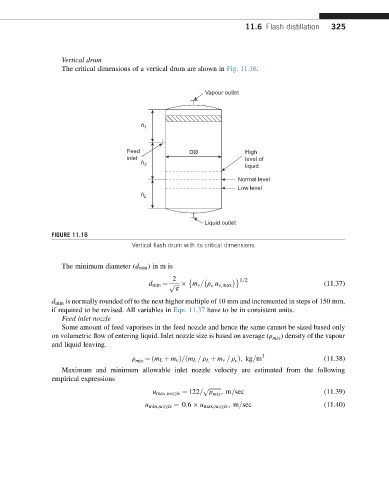
                  The critical dimensions of a vertical drum are shown in Fig. 11.16.


                                                          Vapour outlet


                                        h
                                         1

                                    Feed             DØ              High
                                    inlet                            level of
                                                                     liquid
                                        h 2
                                                                   Normal level
                                                                   Low level
                                        h
                                         L

                                                          Liquid outlet
               FIGURE 11.16
                                      Vertical flash drum with its critical dimensions.


                  The minimum diameter (d min )in m is
                                                 2                	 1=2
                                                           v:
                                          d min ¼ ffiffiffip   m v = r u v;max                   (11.37)
                                                  p
               d min is normally rounded off to the next higher multiple of 10 mm and incremented in steps of 150 mm,
               if required to be revised. All variables in Eqn. 11.37 have to be in consistent units.
                  Feed inlet nozzle
                  Some amount of feed vaporises in the feed nozzle and hence the same cannot be sized based only
                                                                               ) density of the vapour
                                                                             mix
               on volumetric flow of entering liquid. Inlet nozzle size is based on average (r
               and liquid leaving.
                                         ¼ðm L þ m v Þ=ðm L = r þ m v = r Þ; kg=m 3        (11.38)
                                       mix                L       v
                                      r
                  Maximum and minimum allowable inlet nozzle velocity are estimated from the following
               empirical expressions
                                                         p ffiffiffiffiffiffiffiffi
                                                            mix ; m=sec                    (11.39)
                                           u max;nozzle ¼ 122= r
                                         u min;nozzle ¼ 0:6   u max;nozzle ; m=sec         (11.40)
   318   319   320   321   322   323   324   325   326   327   328