
Page 194 -
P. 194
176 6 Advanced Process Discovery Techniques
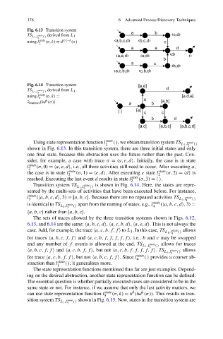
Fig. 6.13 Transition system
TS L 1 ,l 2 state () derived from L 1
using l state (σ,k) = tl |σ|−k (σ)
2
Fig. 6.14 Transition system
TS L 1 ,l state () derived from L 1
3
using l state (σ,k) =
3
k
∂ multiset (hd (σ))
Using state representation function l state (), we obtain transition system TS state
2 L 1 ,l 2 ()
showninFig. 6.13. In this transition system, there are three initial states and only
one final state, because this abstraction uses the future rather than the past. Con-
sider, for example, a case with trace σ = a,e,d . Initially, the case is in state
l state (σ,0) = a,e,d , i.e., all three activities still need to occur. After executing a,
2
the case is in state l state (σ,1) = e,d . After executing e state l state (σ,2) = d is
2 2
reached. Executing the last event d results in state l state (σ,3) = .
2
Transition system TS state is showninFig. 6.14. Here, the states are repre-
L 1 ,l 3 ()
sented by the multi-sets of activities that have been executed before. For instance,
l state ( a,b,c,d ,3) =[a,b,c]. Because there are no repeated activities TS state
3 L 1 ,l 4 ()
is identical to TS L 1 ,l 3 state apart from the naming of states, e.g., l state ( a,b,c,d ,3) =
()
4
{a,b,c} rather than [a,b,c].
The sets of traces allowed by the three transition systems shown in Figs. 6.12,
6.13, and 6.14 are the same: a,b,c,d , a,c,b,d , a,e,d . This is not always the
case. Add, for example, the trace a,c,b,f,f to L 1 . In this case, TS L 1 ,l 4 state allows
()
for traces a,b,c,f,f and a,c,b,f,f,f,f,f , i.e., b and c may be swapped
and any number of f events is allowed at the end. TS L 1 ,l state () allows for traces
3
a,b,c,f,f and a,c,b,f,f , but not a,c,b,f,f,f,f,f . TS L 1 ,l state () allows
1
for trace a,c,b,f,f , but not a,b,c,f,f . Since l 4 state () provides a coarser ab-
straction than l state (), it generalizes more.
1
The state representation functions mentioned thus far are just examples. Depend-
ing on the desired abstraction, another state representation function can be defined.
The essential question is whether partially executed cases are considered to be in the
same state or not. For instance, if we assume that only the last activity matters, we
k
1
can use state representation function l state (σ,k) = tl (hd (σ)). This results in tran-
5
sition system TS L 1 ,l state () shown in Fig. 6.15. Now, states in the transition system are
5