
Page 265 -
P. 265
9.3 Detect 247
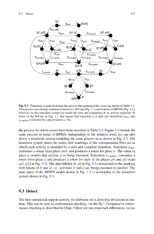
Fig. 9.3 Transition system modeling the process that generated the event log shown in Table 9.1.
This process was already modeled in terms of a WF-net (Fig. 1.1) and in terms of BPMN (Fig. 1.2).
However, in this transition system we model the start and completion of an activity explicitly. In
terms of the WF-net in Fig. 1.1, this means that transition a is split into transitions a start and
a complete connected by a place named a.Etc.
the process for which events have been recorded in Table 9.1. Figure 1.2 models the
same process in terms of BPMN. Independent of the notation used, we can also
derive a transition system modeling the same process as is shown in Fig. 9.3.The
transition system labels the nodes with markings of the corresponding Petri net in
which each activity is modeled by a start and complete transition. Transition a start
consumes a token from place start and produces a token for place a.The tokenin
place a models that activity a is being executed. Transition a complete consumes a
token from place a and produces a token for each of the places p1 and p2(state
[p1,p2] in Fig. 9.3). The state labeled [b,d] in Fig. 9.3 corresponds to the marking
with tokens in b and d, i.e., activities b and d are being executed in parallel. The
state space of the BPMN model shown in Fig. 1.2 is isomorphic to the transition
system shown in Fig. 9.3.
9.3 Detect
The first operational support activity we elaborate on is detecting deviations at run-
time. This can be seen as conformance checking “on-the-fly”. Compared to confor-
mance checking as described in Chap. 7 there are two important differences: (a) we