
Page 12 - Process simulation and control using Aspen
P. 12
INTRODUCTION AND STEPWISE ASPEN PLUS SIMULATION 5
closed-loop control, Aspen Dynamics (formerly DynaPLUS) will be used in several
subsequent chapters. The standard Aspen notation is used throughout this book. For
example, distillation column stages are counted from the top of the column: the
condenser is Stage 1 and the reboiler is the last stage.
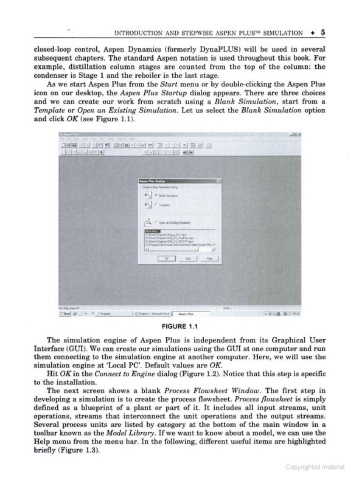
As we start Aspen Plus from the Start menu or by double-clicking the Aspen Plus
icon on our desktop, the Aspen Plus Startup dialog appears. There are three choices
and we can create our work from scratch using a Blank Simulation, start from a
Template or Open an Existing Simulation. Let us select the Blank Simulation option
and click OK (see Figure 1.1).
MM
MM 'Ml I I-
FIGURE 1.1
The simulation engine of Aspen Plus is independent from its Graphical User
Interface (GUI). We can create our simulations using the GUI at one computer and run
them connecting to the simulation engine at another computer. Here, we will use the
'
simulation engine at Local PC'. Default values are OK.
Hit OK in the Connect to Engine dialog (Figure 1.2). Notice that this step is specific
to the installation.
The next screen shows a blank Process Flowsheet Window. The first step in
developing a simulation is to create the process flowsheet. Process flowsheet is simply
defined as a blueprint of a plant or part of it. It includes all input streams, unit
operations, streams that interconnect the unit operations and the output streams.
Several process units are listed by category at the bottom of the main window in a
toolbar known as the Model Library. If we want to know about a model, we can use the
Help menu from the menu bar. In the following, different useful items are highlighted
briefly (Figure 1.3).
Copyrighted material