Page 16 - Process simulation and control using Aspen
P. 16

INTRODUCTION AND STEPVV1SE ASPEN PLUSIM SIMULATION          9

               -Hi                                                           1


                                                       1  #
                                                         ;1  L  -
                                           . I '
                                         i.-
                                       .
                                          I  i  -


                                             FIGURE 1.6
            Then click OK. Again, hit OK when the Aspen Plus engine window pops up and
        subsequently, proceed to create the flowsheet.
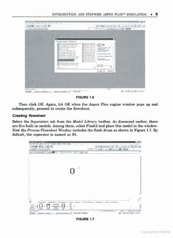
        Creating flowsheet
        Select the Separators tab from the Model Library toolbar. As discussed earlier, there
        are five built-in models. Among them, select Flash2 and place this model in the window.
        Now the Process Flowsheet Window includes the flash drum as shown in Figure 1.7. By
        default, the separator is named as Bl.


                                                                                '
                   nia*lHl mU  -JM ??1                  ra-i-m * -ai-o "d 3  I l-l  SI Hi bl'
                                                                                 3


                                         0


                                                              - I --i
                        0 9 «=>. 8 - C .                                          1


                                             FIGURE 1.7


                                                                                  Copyrlghled
   11   12   13   14   15   16   17   18   19   20   21