
Page 19 - Process simulation and control using Aspen
P. 19
12 PROCESS SIMULATION AND CONTROL USING ASPEN
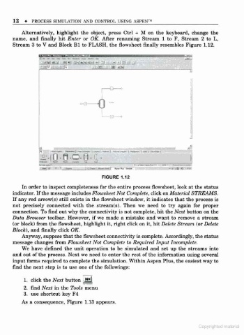
Alternatively, highlight the object, press Ctrl + M on the keyboard, change the
name, and finally hit Enter or OK. After renaming Stream 1 to F, Stream 2 to L,
Stream 3 to V and Block Bl to FLASH, the flowsheet finally resembles Figure 1.12.
~
- -
c-Q- 0
a -=
Si . , S
jjH* - <*- i -ja- --md.n -fw »
FIGURE 1.12
In order to inspect completeness for the entire process flowsheet, look at the status
indicator. If the message includes Flowsheet Not Complete, click on Material STREAMS.
If any red arrow(s) still exists in the flowsheet window, it indicates that the process is
not precisely connected with the stream(s). Then we need to try again for proper
connection. To find out why the connectivity is not complete, hit the Next button on the
Data Browser toolbar. However, if we made a mistake and want to remove a stream
(or block) from the flowsheet, highlight it. right click on it. hit Delete Stream (or Delete
Block), and finally click OK.
Anyway, suppose that the flowsheet connectivity is complete. Accordingly, the status
message changes from Flowsheet Not Complete to Required Input Incomplete.
We have defined the unit operation to be simulated and set up the streams into
and out of the process. Next we need to enter the rest of the information using several
input forms required to complete the simulation. Within Aspen Plus, the easiest way to
find the next step is to use one of the followings:
1 . click the Next button
2 . find Next in the Tools menu
3 . use shortcut key F4
As a consequence. Figure 1.13 appears.
Copynghied material