Page 120 - Process simulation and control using Aspen
P. 120

110       PROCESS SIMULATION AND CONTROL USING ASPEN

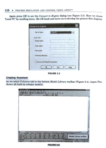
          Again press OK to see the Connect to Engine dialog (see Figure 3.3). Here we choose

      T ,ocal PC by scrolling down. Hit OK knob and move on to develop the process flow diagram .
                                                                        a
                             Connect to Engine


                                  Server type:

                                 User Info
                                  Node name:

                                  User name:

                                  Password:
                                  Working directory:


                                    Save as Default Connection

                                        (   OK   1     Exit       Help


                                              FIGURE 3.3

       Creating flowsheet
       As we select Columns tab in the bottom Model Library toolbar (Figure 3.4), Aspen Plus
       shows all built-in column models.


                   «a 6t Mr- 0*s  locii Rfi Rewhart  Ltrary Wxto- H«c> f


                                                                  Model Library toolbar
                                                    r
                    f
                   SttEAMS  1 DiTVU  Ci-J  R»fEjJikI  M tfug  Sffru  PWtf.te  Rurf-  Bwctfi -
                                              FIGURE 3.4
   115   116   117   118   119   120   121   122   123   124   125