
Page 121 - Process simulation and control using Aspen
P. 121
ASPEN PLUS SIMULATION OK DISTILLATION MODELS 111
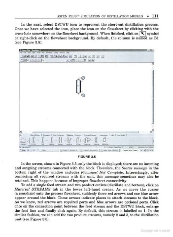
In the next, select DSTWU icon to represent the short-cut distillation process.
Once we have selected the icon, place the icon on the flowsheet by clicking with the
cross-hair somewhere on the flowsheet background. When finished, click on K | symbol
or right-click on the flowsheet background. By default, the column is named as Bl
(see Figure 3.5).
i\n 'amiami I
Hi tM Dn <oaa 'hr nrann lw -«
f
Dfagyai aial id g] aifici K!--! "i i |m| ! v\ *\
r|rrFf,.|..|..h HT 'MPl I Bl -fW
UJ iT
-
_
- CH
"SAW. ' DIIMI Out "*l<m 1M MtfMi IW l*. ..
i c-.i C- a'aMAcwi a IM AM ru- MMC*
FIGURE 3.5
In the screen, shown in Figure 3.5. only the block is displayed; there are no incoming
and outgoing streams connected with the block. Therefore, the Status message in the
bottom right of the window includes Flowsheet Not Complete. Interestingly, after
connecting all required streams with the unit, this message sometime may also be
retained. This happens because of improper flowsheet connectivity.
To add a single feed stream and two product outlets (distillate and bottom), click on
Material STREAMS tab in the lower left-hand corner. As we move the cursor
(a crosshair) onto the process flowsheet, suddenly three red arrows and one blue arrow
appear around the block. These arrows indicate places to attach streams to the block.
As we know, red arrows are required ports and blue arrows are optional ports. Click
once on the connection point between the feed stream and the DSTWU block, enlarge
the feed line and finally click again. By default, this stream is labelled as 1. In the
similar fashion, we can add the two product streams, namely 2 and 3, to the distillation
unit (see Figure 3.6).
Copyrighted malarial